
Aluminum damper blade cutting is a small step with several downstream interfaces. A blade blank has to fit its frame, carry an axle or linkage where specified, and leave the intended edge available for a seal. A saw trial that reports only the nominal length can miss damage at precisely the surfaces that matter during assembly.
This guide is for a damper maker or fabricator preparing an extrusion cutting RFQ. It explains what to define before a trial, how to support the blade without distorting it, and what to inspect before accepting cut blanks. It concerns blades rather than frame rails; for the separate frame decision, see our aluminum damper frame cutting guide. The damper designer’s approved drawings and assembly criteria remain the authority.
Start with the blade system, not a generic extrusion length
Ask for a section drawing of the exact blade extrusion, including revision, alloy and temper, nominal blank length, cut direction, and every feature that will be handled after cutting. Identify which edge meets a blade seal, whether a seal is installed before or after sawing, and where end caps, axle hardware, bearings or linkage will be assembled. Mark which dimensions are measured on the bare blank and which are checked after assembly. The answer can differ across damper families, so do not carry a setup or tolerance from one profile to another.
For context, Greenheck’s VCD-43 submittal shows an extruded aluminum airfoil blade as one part of a damper with separate blade seals, axles, bearings and linkage. Its material and performance figures apply to that named product, not to an arbitrary extrusion or Jiurun cutting equipment. A purchaser should use its own approved drawing and bill of materials to decide which interfaces a cut can affect.
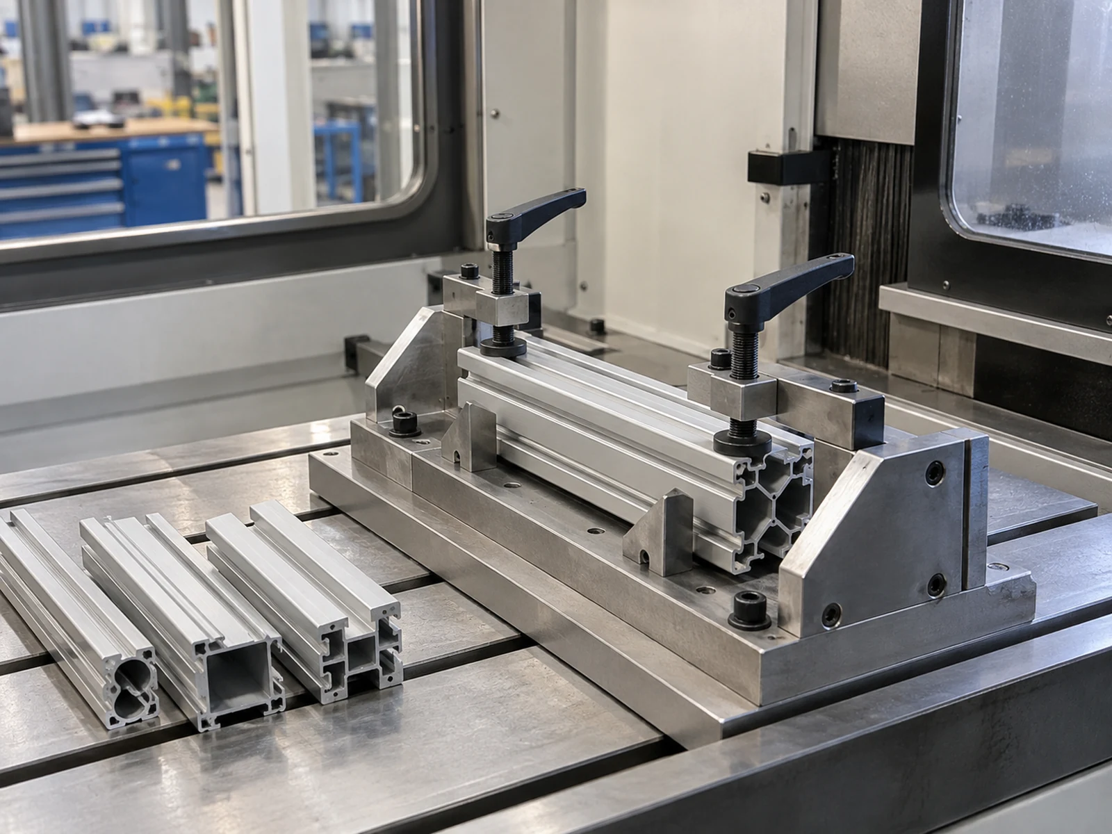
Support the section without crushing its functional edges
First map the blade’s load-bearing walls and fragile lips on a cross-section. A thin edge or seal groove should not automatically become a clamp datum. Where a profile has a crowned or airfoil surface, a flat jaw can touch only a small area; tightening it harder may bend the section while leaving a misleadingly stable-looking setup. Design contact pads and end support from the actual section, then check that the blank remains seated while the blade enters and exits the cut.
Document the orientation of the leading edge, trailing edge and any groove relative to the feed direction. If stock has twist or bow, specify the incoming condition and how the operator locates the part. A length measured against a distorted stock end may be repeatable on the saw yet still be wrong at assembly. An aluminum damper blade cutting trial should record the support locations, clamping pressure or setting where applicable, and the first and last acceptable pieces from a run; there is no universal clamp setting for all damper blades.

Keep the seal interface clear and inspect the cut edge
A cut can leave burrs, a rolled lip, chips in a groove or a sharp corner where a seal later seats. Agree with the damper designer whether the cut blank is to be deburred, cleaned or otherwise finished, and which face must remain untouched. Do not specify an aggressive edge break merely because it looks smoother: removing material at a seal land can change the intended contact. If seals are pre-installed, the process route needs explicit approval and a means to inspect seal damage; if they are installed afterward, the bare groove still needs a clean handoff.
Greenheck’s blade seal service instructions show how seal placement and seal variants depend on the damper model. That is a useful reminder to identify the actual seal before approving a cut process. It is not a tolerance sheet for unrelated blades.
Inspect both ends in the orientation used on the drawing. Photograph the seal edge and any open chamber, record burr direction, and confirm that loose chips have been removed without damaging a groove. Where edge condition is critical, use a sample with the intended seal and mating blade or frame, then have the assembly owner decide whether the contact is acceptable. A photograph of a clean aluminum face alone cannot establish leakage or operating performance of an assembled damper.
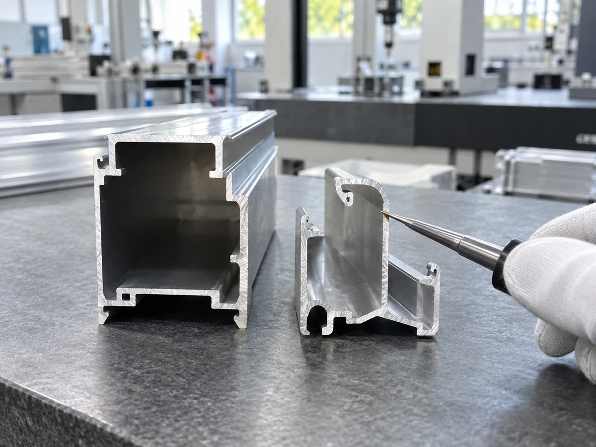
Check the axle and end-hardware handoff
Some blade designs carry an axle through the extrusion; others use end hardware, clips, or a distinct drive arrangement. For aluminum damper blade cutting, the RFQ should say which end receives which part, whether end caps are fitted, and what post-cut operations are required. Define the drawing datums for the blank length and any later holes or slots. If the axle or cap references the sawn face, end squareness and burr control can influence assembly. If it references a separate machined feature, the cut-length acceptance plan may differ.
Do not infer bearing fit or operating torque from a saw demonstration. Make a representative assembly from trial blanks and check insertion, alignment, rotation and clearance with the actual approved components. Record any interference and its location: blade end, seal edge, cap seat, or axle feature. This lets the saw supplier adjust a relevant cutting or holding variable rather than being asked to solve an unspecified assembly symptom.
Run a useful supplier trial
- Issue one controlled drawing package. Include blade section and revision, stock condition, blank lengths, orientation, allowable end work and the exact inspection points.
- Agree on a sample plan. Include short and long lengths if both are sold, plus pieces from the start and end of a representative feed run. State who measures the parts and by which method.
- Watch the cut and the handoff. Record clamp contact, support span, feed behavior, chip removal and whether the functional edge touches a fixture or collection surface.
- Inspect before and after assembly. Check blank length, end squareness and edge condition against the buyer’s drawing; then check the actual seal and axle or end-cap fit on assembled samples.
- Approve only the defined configuration. If section revision, seal, hardware or material condition changes, review whether the trial still applies.
The video below shows Jiurun aluminum cutting equipment and its feeding/cutting sequence. It is equipment footage for process discussion, not a trial of this damper blade, its seal, axle fit, leakage or a promised performance result.
What to send with an aluminum damper blade cutting RFQ
Send the blade section drawing and revision; alloy, temper and stock length; requested blank lengths and volume; the seal and end-hardware sequence; the dimensions and edge conditions to accept; representative sample quantities; and the person who approves the assembled trial. If a customer specification calls for leakage, airflow or operating tests, name the complete damper test method and responsible party separately. A saw cut is one manufacturing input, not evidence of a complete damper rating.
Need a cutting setup review? Share the controlled blade drawing, target lengths and the seal/axle assembly requirements with JiurunCut. We can discuss what a representative cutting trial should measure and which support details need to be verified on your actual extrusion.