
01
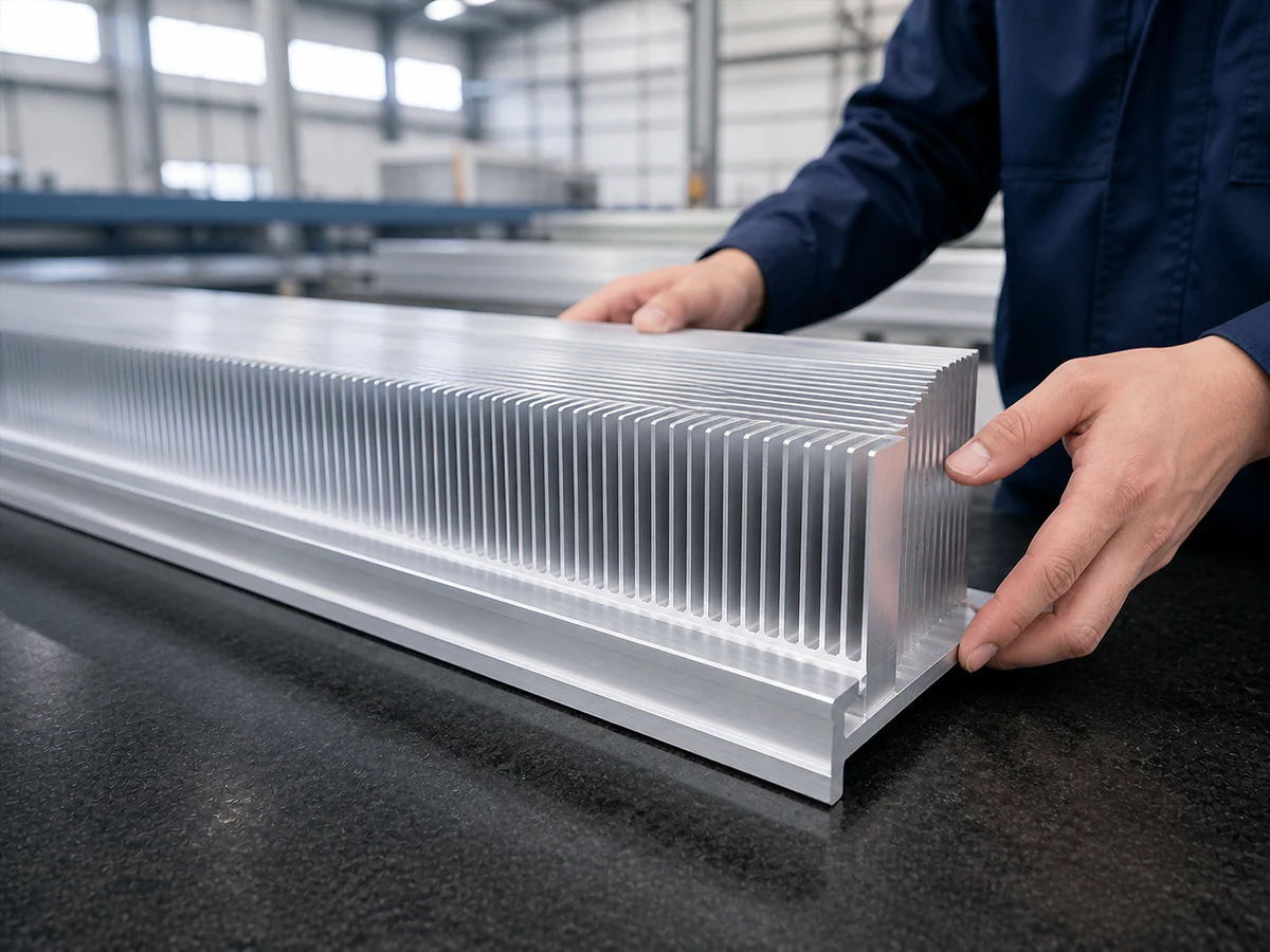
Dense Thin-Fin Profiles
CHALLENGE
Closely spaced fins need safe contact zones and controlled support.
WHAT WE REVIEW
Fin spacing · base contact · cut face
Send Your Heat Sink DrawingHEAT SINK ALUMINUM CUTTING ENGINEERING
Send the heat sink section and finished-length requirement. JiurunCut reviews fin geometry, base support, safe clamp contact, burr acceptance and collection before recommending a semi-automatic cutting direction and sample plan.
Start with: Fin geometry · Base section · Finished length · Burr criteria · Collection
01 — UNDERSTAND THE PART
ENGINEERING INPUTS
Fin height · spacing · direction
Base thickness · strong clamping zones
Finished length · burr acceptance · cut face
Collection · surface protection · batch size
BUYER FIT
Start with the weakest fin and the strongest safe clamping zone—not the overall profile size alone.
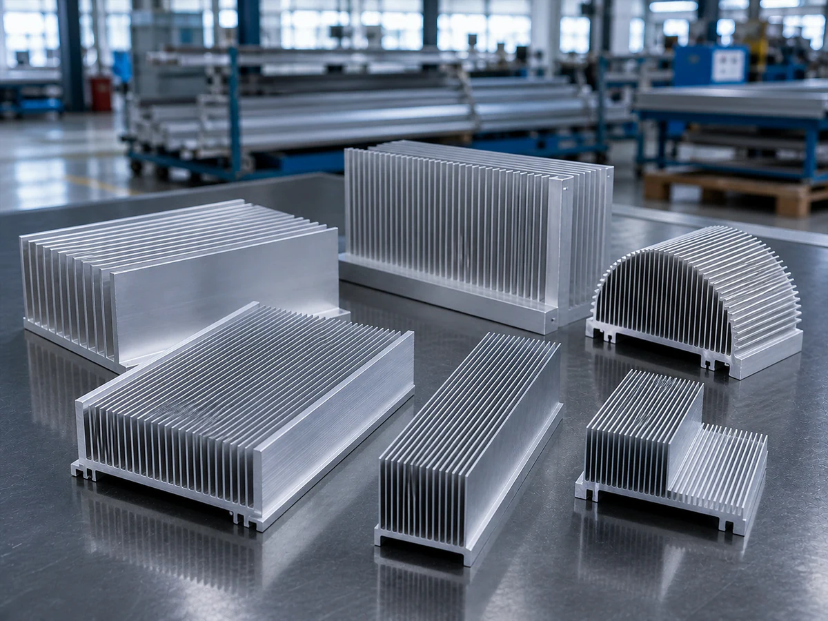
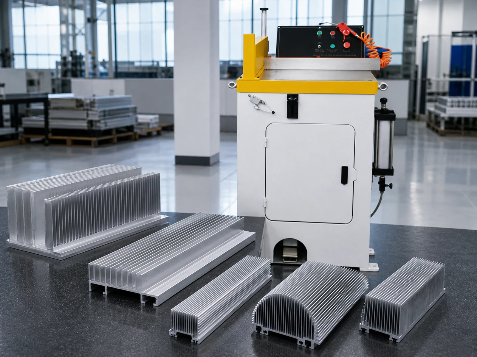
High-fin, dense thin-fin, wide-base and power-electronics heat sink extrusions.
Fin crushing, stable base support, burr, deformation, clean handling and repeat length.
Identify safe contact zones, support the base, control clamping and verify the cut face.
Flexible or repeat-production direction follows from profile behavior and order volume.
Cross-section, fin height and spacing, base thickness, finished length, burr criteria and quantities.
TYPICAL HEAT SINK PARTS
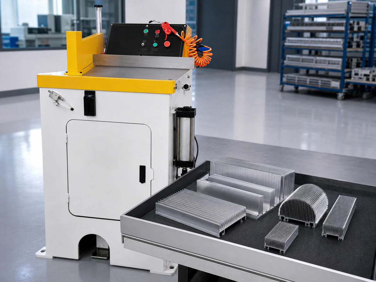
Part geometry decides the support, clamping, datum and cut sequence before a machine direction is selected.
CHALLENGE
Closely spaced fins need safe contact zones and controlled support.
WHAT WE REVIEW
Fin spacing · base contact · cut face
Send Your Heat Sink Drawing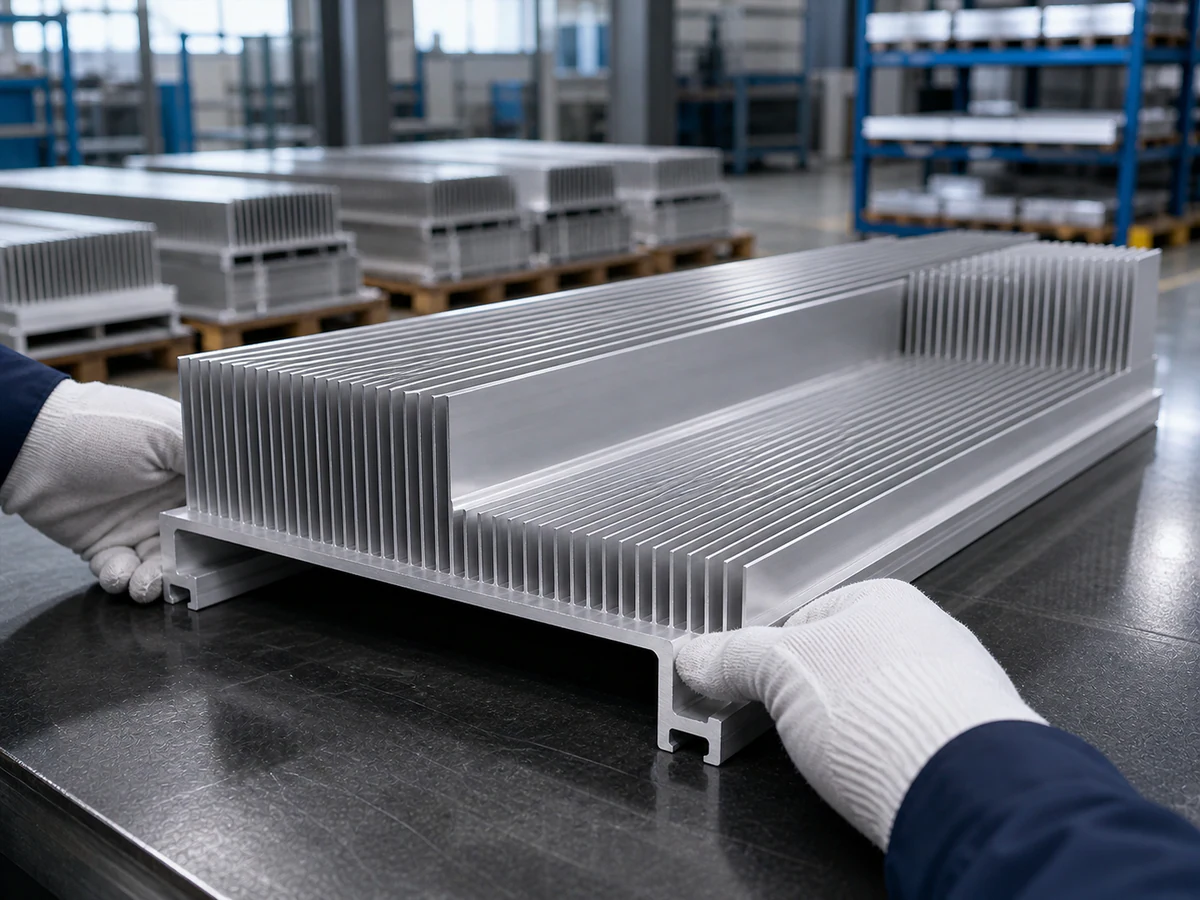
CHALLENGE
Uneven geometry changes the support and clamping contact.
WHAT WE REVIEW
Fin direction · balanced support · clamp force
Send Your Heat Sink Drawing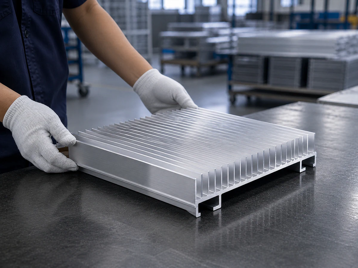
CHALLENGE
A wide base needs stable support and agreed deformation checks.
WHAT WE REVIEW
Base stiffness · finished length · flatness
Send Your Heat Sink Drawing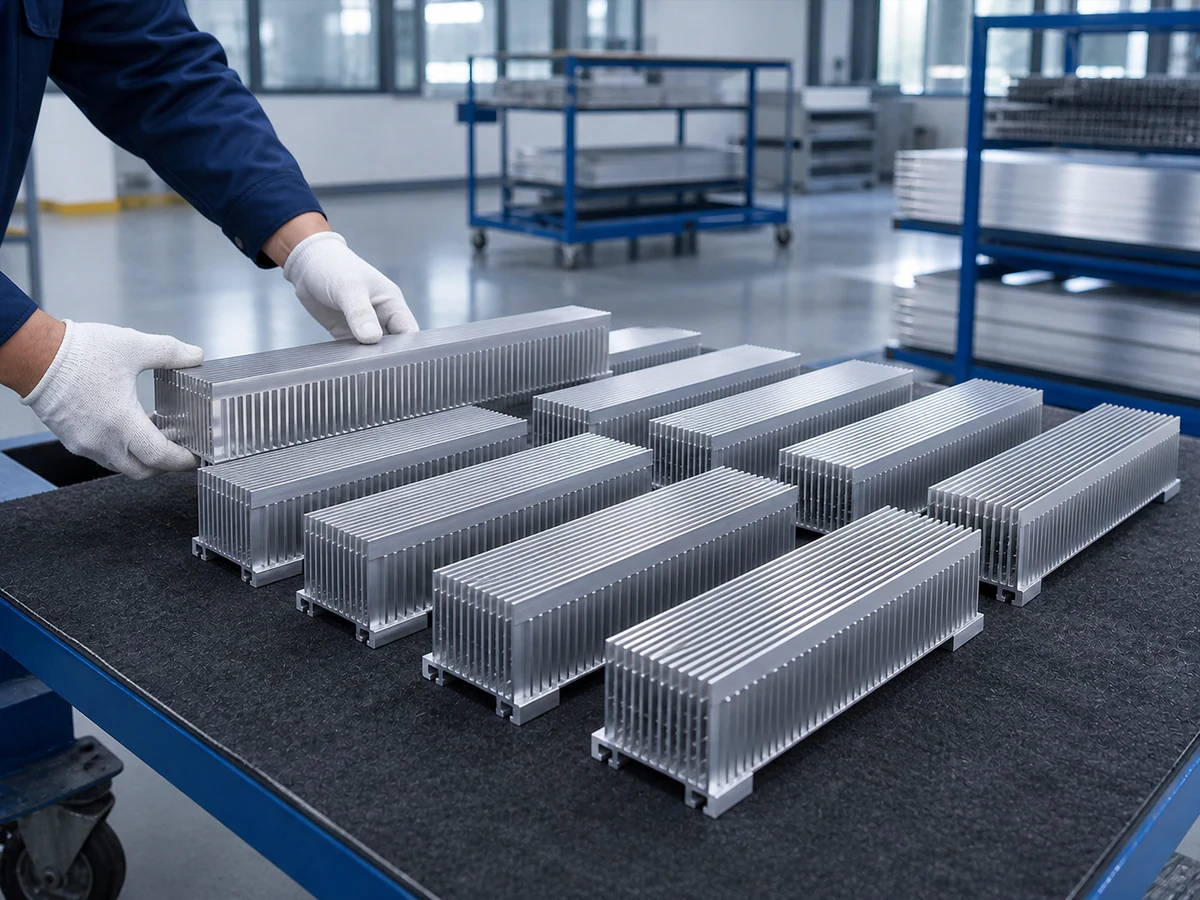
CHALLENGE
Finished parts need protected collection and consistent inspection.
WHAT WE REVIEW
Repeat lengths · fin condition · part separation
Send Your Heat Sink DrawingENGINEERING DECISIONS
The machine is selected around the real profile, not around a generic catalog specification.
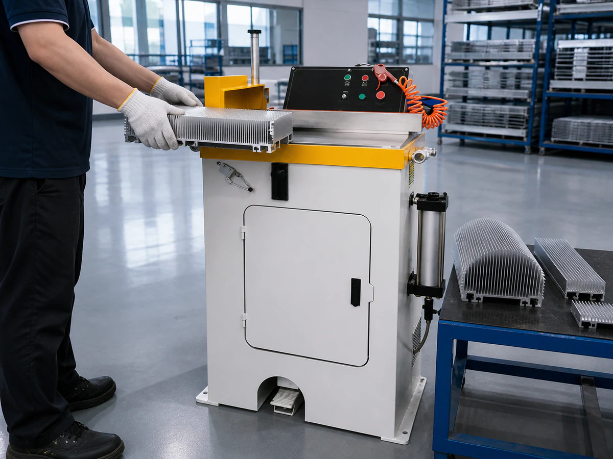
THE RISK
Clamp contact on a weak fin can permanently bend or close the fin spacing.
JIURUN ENGINEERING RESPONSE
Use the section drawing to identify base or reinforced zones and validate clamp force on real material.
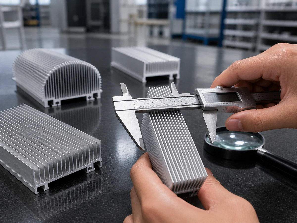
THE RISK
Burrs and edge damage can affect handling, assembly or downstream finishing.
JIURUN ENGINEERING RESPONSE
Agree the cut-face acceptance method and inspect representative samples under production conditions.
THE RISK
A good cut can still be damaged when the finished part drops, slides or strikes another part.
JIURUN ENGINEERING RESPONSE
Plan collection and separation around part weight, fin direction and appearance requirements.
THE RISK
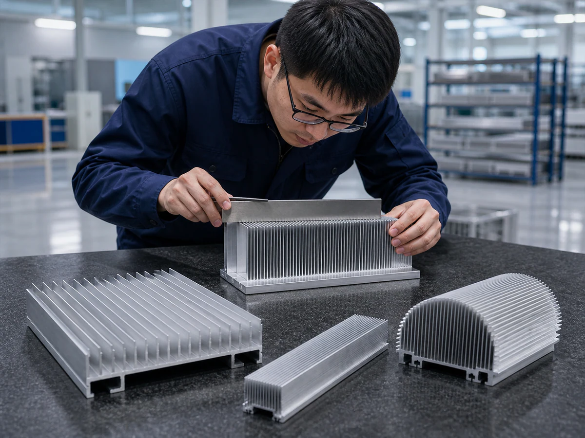
Uneven support can twist the base or shift the fin field during the cutting cycle.
JIURUN ENGINEERING RESPONSE
Support the load-bearing section and compare geometry before and after representative cutting.
02 — BUILD THE CUTTING STRATEGY
ENGINEERING DECISION PATH
Each decision follows from the finished part, its datum and the production requirement.
We start with the real part and its cutting requirement.
Record fin height, spacing, direction, base thickness and profile width.
Mark reinforced surfaces that can accept support and clamp load.
Plan how the fin field enters, rests and exits the cutting area.
Define finished length, burr acceptance and cut-face expectation.
Apply controlled contact on real material and inspect for fin movement.
Prevent the cut part from dropping onto fins or striking the next piece.
Check burr, base flatness, fin condition and repeat length.
Select flexible or repeat-production equipment after the sample behavior is understood.
CUTTING STRATEGY
Review the real heat sink geometry, support, cutting requirements and agreed inspection method before selecting the machine configuration.
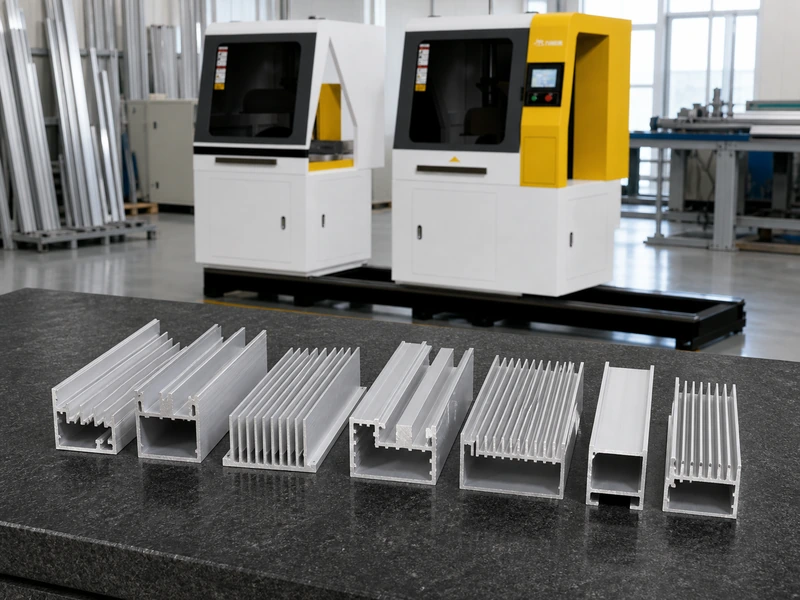
WHY THIS DIRECTIONChanging heat sink sections and shorter orders prioritize controllable setup, safe clamping and careful collection.
Send Your Heat Sink Drawing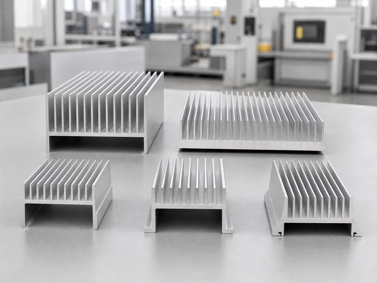
WHY THIS DIRECTIONStable profile families and recurring finished lengths can prioritize repeat positioning and consistent handling.
Send Your Heat Sink Drawing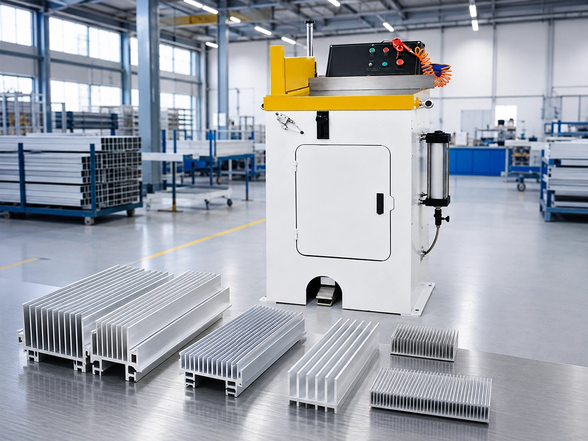
WHY THIS DIRECTIONWhere fin damage is the primary risk, support, clamp and collection design take priority over nominal cycle speed.
Send Your Heat Sink DrawingMACHINE DIRECTION
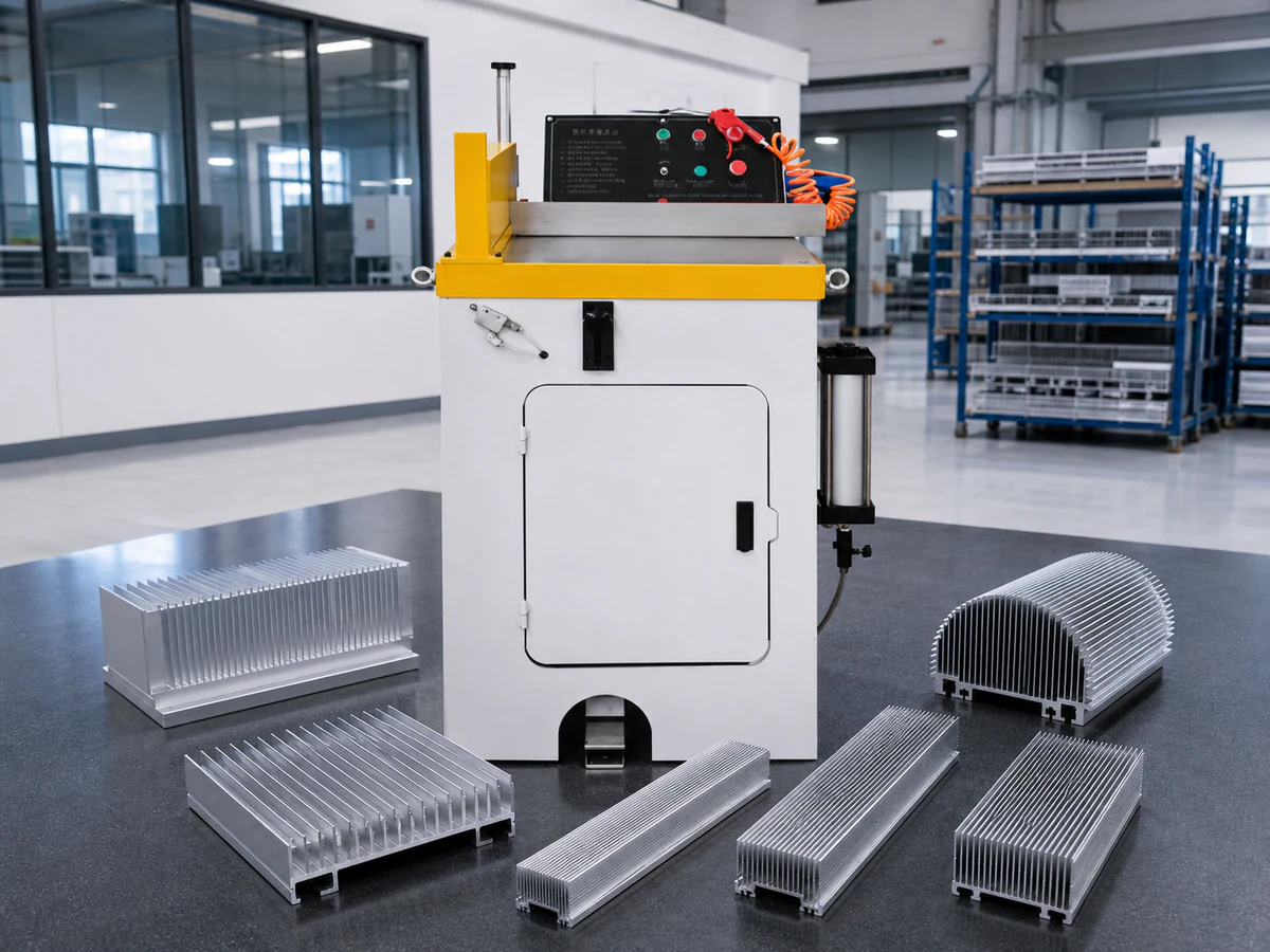
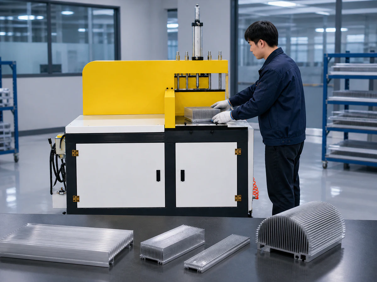
The board below shows two starting directions, not a final machine promise.
03 — VERIFY BEFORE PRODUCTION
ENGINEERING PROCESS
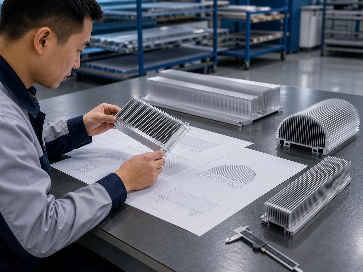
A practical review sequence for profile geometry, clamping, cutting and inspection.
Send the cross-section, finished-part or joint drawing, stock and finished lengths, quantities and inspection requirements.
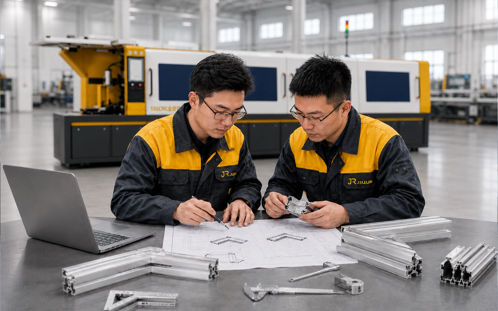
Review geometry, safe contact areas, the cutting list and the agreed acceptance criteria.
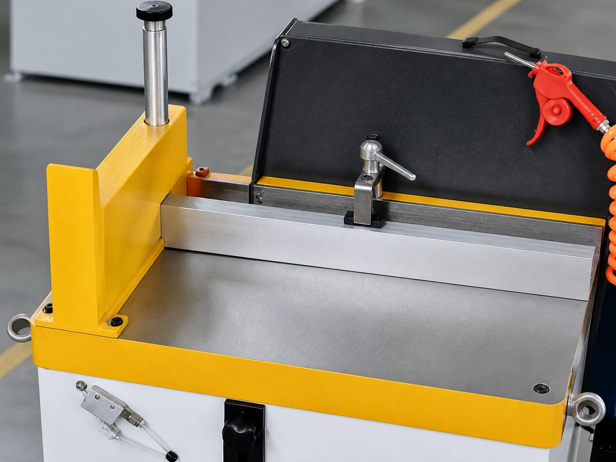
Plan the machine direction, support, clamping, feeding or positioning and protected collection.
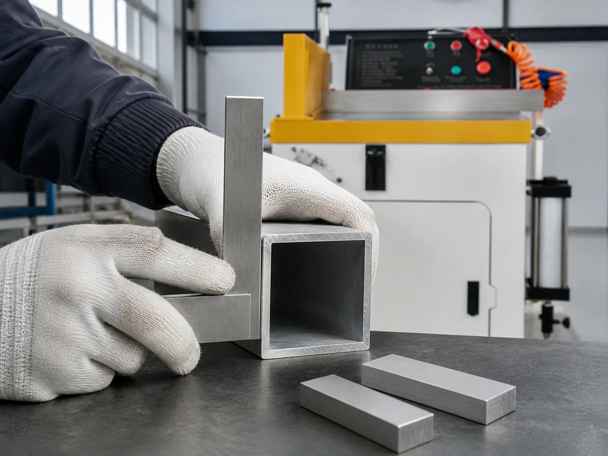
Check representative parts for finished dimensions, cut-face condition, repeatability and the required fit.
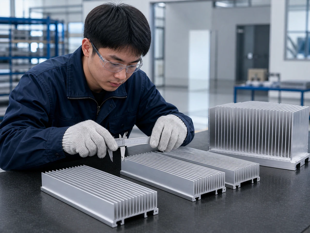
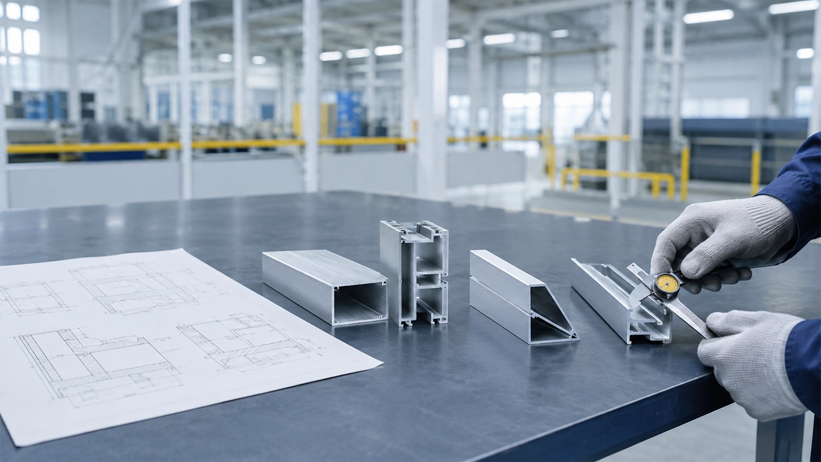
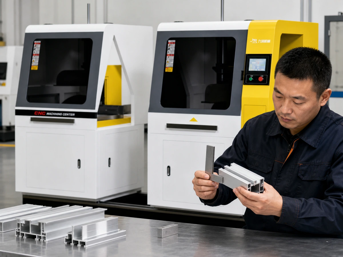
Engineering images illustrate the review and inspection topics. Representative sample results are agreed for the actual application.
PROVE BEFORE PRODUCTION
Agree representative sections, finished lengths and inspection criteria before sample cutting. Confirm the full support, cutting and collection sequence.
A Representative Test Should Include
Inspect burr at the base, fin tips and narrow spaces.
Measure consecutive parts from the agreed datum.
Compare fin spacing and straightness before and after cutting.
Check flatness, twist and contact marks using the agreed method.
Inspect finished fins and surfaces after the complete handling cycle.
BEFORE SHIPMENT
FASTER ENGINEERING REVIEW
Complete inputs help the engineering team review support, clamping, machine direction and sample-cut criteria without guessing.
Show fin height, spacing, direction, base thickness and overall profile size.
Mark surfaces that may accept support and clamping without functional damage.
Provide short, long and recurring lengths with order quantities.
Describe acceptable burr, blade marks and downstream finishing.
Identify visible faces, fin orientation and collection constraints.
Share damaged parts, photos or the present source of deformation and burr.
BUYER FAQ
Technical answers based on the real profile, production task and inspection requirements.
Clamping begins with the real cross-section, not a general rule based on overall width. JiurunCut asks the customer to mark fin height, spacing, base thickness and any reinforced contact zones. Support and clamp force are directed toward the base or another structurally safe area wherever the section permits. A representative profile is then clamped and cut so fin movement, marks and base deformation can be inspected. The final contact design is confirmed only after the real extrusion behaves acceptably under the agreed cutting conditions.
Yes, but the support concept depends on the fin direction, spacing, profile width, base stiffness and how the extrusion enters the cutting area. Direct contact with a tall fin field may be unacceptable, while base support or profile-specific contact parts may be practical. JiurunCut reviews the section to keep the part stable without transferring harmful load into weak fins. Sample cutting includes pre- and post-cut visual checks and, when required, simple dimensional comparisons to confirm that the fin field and base remain within the agreed condition.
The customer should define how the finished cut will be used and what burr or edge condition is acceptable for handling, assembly and any downstream machining. JiurunCut then records the inspection method before sample cutting. Representative parts are checked at the base, fin tips and internal spaces where burr may present differently. The result is not described only as clean or rough; photos, agreed visual criteria or measured limits are used where practical. Blade and process direction are finalized around the supplied material and real acceptance requirement.
It can if the extrusion is supported unevenly, clamped on a weak area or allowed to move under cutting load. A wide or heavy base is not automatically immune to twist. JiurunCut reviews the base thickness, internal cavities, fin arrangement and safe contact surfaces, then tests the proposed setup on representative stock. Base condition can be compared before and after cutting using the agreed inspection method. If deformation appears, support position, contact geometry, clamping force or handling must be adjusted before production approval.
Post-cut handling is part of the process design because a correctly cut heat sink can still be damaged when it drops, slides or strikes another part. JiurunCut reviews part weight, fin direction, finished length, visible faces and batch size to plan collection. Separation pads, guided discharge or manual collection may be considered depending on the configuration and output. The representative test follows the part through the complete cycle and inspects fin tips, base edges and appearance surfaces after collection, not only while the part remains at the saw.
Possibly, when the profiles share compatible base support and safe clamping zones. A small change in fin height or cavity position can alter how load passes through the extrusion, so program changes alone are not sufficient. Send every important cross-section and identify the most fragile and highest-volume parts. JiurunCut groups compatible sections, identifies required adjustments or inserts and proposes a practical changeover. The machine direction is confirmed only after representative profiles have been clamped and cut without unacceptable fin, base or surface damage.
The finished-length datum and inspection tool are agreed before testing. JiurunCut cuts several consecutive parts under the representative support, clamp and collection setup, then compares measurements rather than selecting one favorable sample. If the order includes several stored lengths, important programs are repeated to confirm the process returns consistently. At the same time, the cut face and fin condition are checked because accurate length alone is not an acceptable result if clamping or handling damages the heat sink. The recorded measurements and inspection photos become the reference for final production approval.
Yes. The model direction depends on profile geometry, safe contact zones, finished lengths, batch size, change frequency and handling. JR-455Q may be a starting direction for flexible small-batch work, while JR-455Y may be considered for recurring heat sink production. These are not unconditional selections. A representative sample verifies whether the support, clamping, cut face, fin condition and collection plan meet the agreed requirement before the final machine configuration is confirmed. The agreed test record is used to confirm the machine scope and factory acceptance criteria.
Send the drawing and available production requirements for engineering review.
ALUMINUM CUTTING MACHINE QUOTE
Tell us what you need to cut. We’ll confirm the details with you, recommend a machine and prepare a quote.
Prefer to chat?
Chat on WhatsAppOnly your name or company and WhatsApp / phone are required. Everything else is optional.