
A conveyor side guide changeover kit often fails at the interfaces, not at the headline rail length. A straight aluminum rail may be cut to its drawing dimension and still leave a step at a neighboring segment, obstruct a bracket adjustment, or put the guide face in a different position after a product change. If you are buying an aluminum saw for these kits, the useful question is whether the cutting process can deliver a repeatable assembly-ready set of straight members under your actual reference and inspection method.
This guide is for teams that cut straight aluminum guide rails or their mounting members in-house. It is not a guide to forming curved rails, machining slots, coating guide faces, or validating a complete conveyor. If the design includes bought-in bends, plastic contact strips, brackets or proprietary conveyor parts, define those as separate supply or downstream operations before judging a saw.
Define the kit before selecting the saw
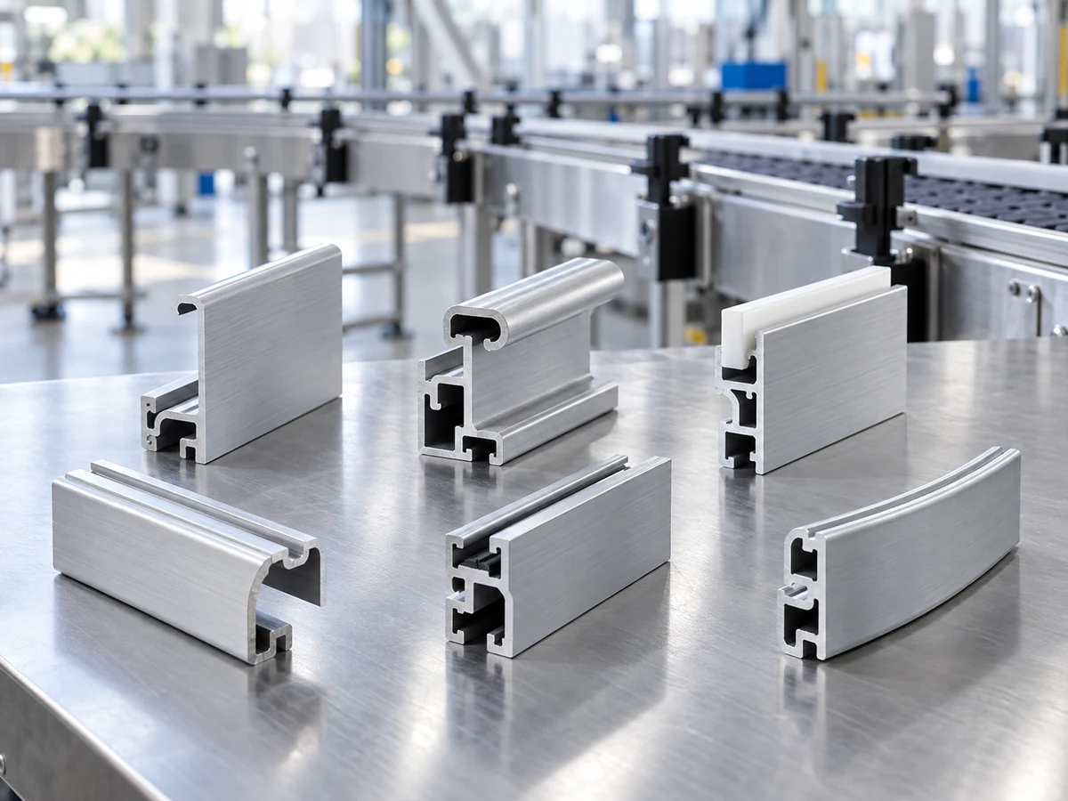
Begin with one approved changeover kit drawing and a bill of materials. Identify each straight aluminum member by cross-section, alloy and temper if known, surface finish, cut length, end condition, quantity per kit and mating location. Mark every curved or flexible portion separately. A single conveyor can use different guide-face materials and mounting components; for example, Dorner describes guide arrangements with an aluminum mounting rail and a separate contact face or adjustable hardware on its own conveyor ranges. That product example illustrates why a rail drawing cannot stand in for the complete guiding assembly. It is not a Jiurun machine specification.
Specify whether the saw operator receives extrusion stock, a preassembled guide with a contact strip, or a bracketed rail. Cutting an assembled part may damage a contact face or hardware and may be outside the proposed process. Give the saw supplier the actual stock state, not just a finished conveyor photograph.
Choose a datum that survives the changeover
For a straight guide, overall length alone is rarely enough. State which face or slot is the primary reference when the extrusion is clamped, which end is measured from, and which feature locates the installed guide. A burr-free visible face may be important, while a hidden fastening face may tolerate a different finish. Those decisions belong on the approved drawing and acceptance sheet, not in an assumed universal tolerance.
If a rail locates from a bracket hole or slot made downstream, say so. The saw can produce the blank and its cut ends; it does not automatically establish the position of a later-machined slot. Conversely, if the installed system locates from the cut end against a stop, squareness and end-face damage become part of the trial. Record the measurement points on a marked sample. This prevents the machine vendor from presenting a feed-position repeatability number as finished-part or assembled-guide accuracy.
Ask the production team to label each sample with profile revision, cut orientation, datum end and intended installation position. Measure it with the same fixture or inspection method used to accept production parts. A sample that looks clean on a bench may still fail the joint or the available bracket adjustment.
Trial the conveyor side guide changeover kit at the joint
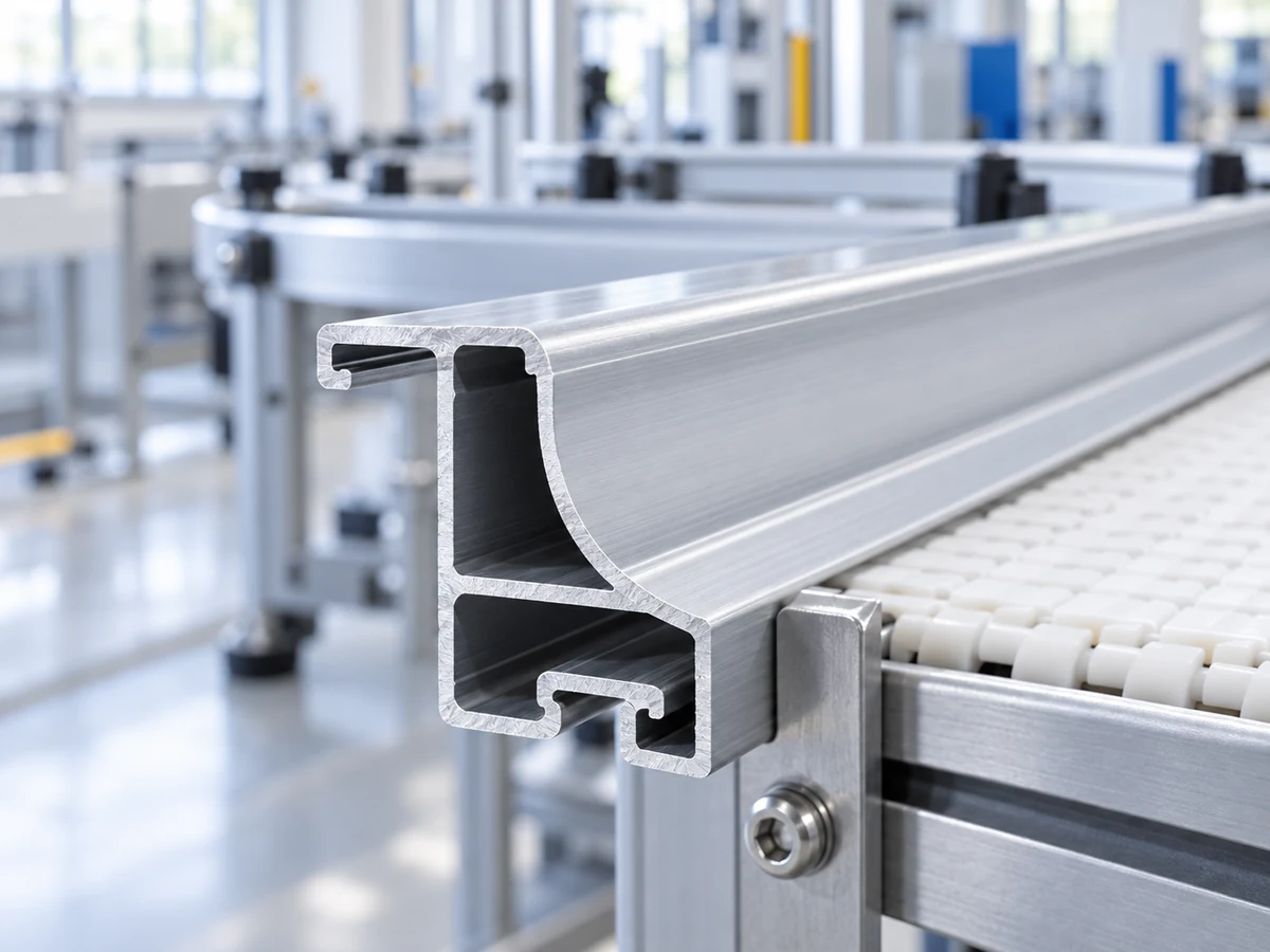
For a conveyor side guide changeover kit, request a trial kit rather than one attractive cut. Include the longest and shortest straight lengths in the family, a profile with the most awkward clamping face, a representative finish, and a joint that has previously been difficult to assemble. For each length, record the intended stock orientation and the actual cut sequence. If the kit is nested from long stock, include the final short piece and the remnant decision in the trial plan; do not assume an advertised minimum remnant applies to this section.
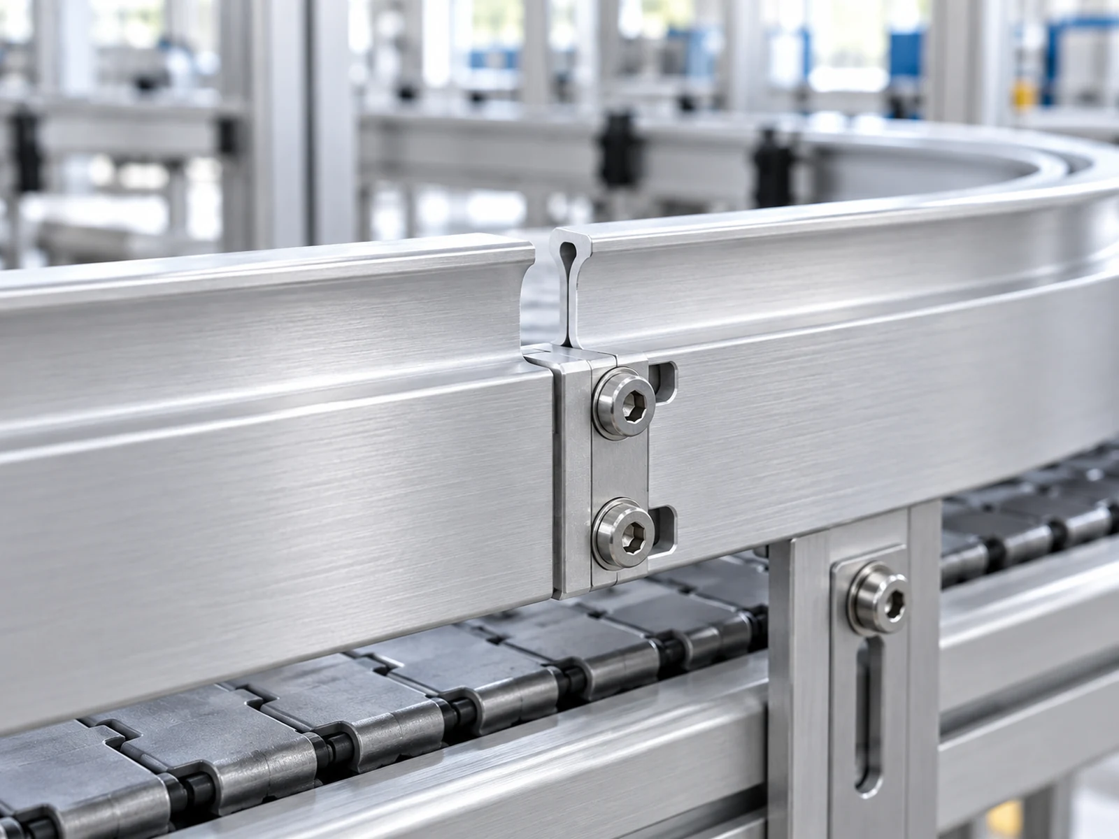
Assemble the trial rails with the actual brackets, fasteners and guide-face components. Check the gap and step at adjoining straight segments, the connection to a separately supplied curve, clearance above the belt or rollers, and whether the bracket still has useful adjustment in both directions. Perform at least one genuine product-width change using the intended kit and record which adjustments are repeatable and which need manual fitting. These are acceptance activities for the buyer to define and witness; they are not results claimed for any existing Jiurun installation.
Use an acceptance matrix instead of a single tolerance
| Decision point | Input to supply | Evidence to request from the trial |
|---|---|---|
| Cut blank | Profile section, stock condition, finished lengths and datum end | Identified samples and measurements at the drawing’s reference points |
| End quality | Visible face, mating face and permitted burr or damage criteria | End-face inspection after the normal deburring sequence, if any |
| Segment joint | Joint drawing and adjacent straight or bought-in curved member | Physical fit with the actual joining components |
| Changeover | Two real product widths, bracket positions and kit list | Observed adjustment and repeat installation, with deviations logged |
| Production mix | Batch sizes, profile changes and stock lengths | Time and scrap recorded under an agreed, repeatable trial method |
Set pass/fail values from your drawing, guide supplier and conveyor application. The matrix separates what the saw can demonstrate at the cut blank from what only the completed assembly can demonstrate. It also makes a purchase comparison fair: each supplier sees the same profiles, stock, reference method and downstream steps.
What to compare in a machine proposal
Confirm the proposed machine’s actual capacity for your profile envelope and clamping geometry, not just a catalog blade diameter. A thin-wall or asymmetric guide extrusion may need a different support or clamp approach from a solid bar. Ask how the visible guide face is protected, how the chosen datum is maintained during feed and cutting, and what changes when switching between profile sections. If angle cuts are required, identify the exact cut angle and model configuration separately; do not infer an angle range from a different machine.
Compare the complete workflow: stock presentation, loading, datum setup, cut, removal, inspection, any deburring, bracket or strip installation, and kit labeling. An automated feed may help a repeated straight-length family, but it does not remove the need to establish the initial reference and verify assembled fit. A manual or semi-automatic route may remain practical for very short, mixed batches; the right choice depends on actual batch mix and labor method rather than a generic cycle-time promise.
Before approving a quotation, ask which clamp or support parts, measurement method, safety enclosure, blade and material-specific setup are included for the trial profile. Treat optional or custom equipment as quotation items, not assumed standard features. See our broader conveyor manufacturing saw selection guide if your scope also includes frame members or roller tubes.
Equipment footage: a general example only
The video below is from Jiurun Machinery’s own YouTube channel and shows general aluminum-saw equipment footage. It is provided to show a machine environment and operating sequence. It does not show this conveyor-guide material, the proposed model or configuration, a customer order, this article’s trial kit, or verified cut quality and performance. Request a trial against your own drawings and stock before making a purchase decision.
Send an RFQ that can produce a meaningful answer
Send the approved profile and assembly drawings, photos of actual stock and contact faces, alloy and finish, straight member lengths, kit quantities, stock lengths, required end condition, joint and bracket details, downstream operations, and your inspection method. State which curves or proprietary parts are supplied by others. Include the product-width change you want to test and ask the supplier to report any clamp, support or setup assumptions.
Ask for an identified sample kit and a trial record against those drawings. The most useful quotation is one that names the machine configuration and its limits, lists optional tooling explicitly, and leaves no ambiguity about what the saw supplies versus what your assembly operation must complete. Send JiurunCut your guide profile drawing and trial requirements to discuss a suitable cutting approach.
Sources and scope
Dorner 3200 Series accessories describes example guide and adjustable hardware arrangements for its specific conveyor products. It supports the general point that the guide assembly has more than a cut rail; it is not a Jiurun capability claim. All trial steps and acceptance questions above are a buyer’s proposed evaluation framework, to be finalized against the buyer’s drawings and real parts.