
Inspection fixture frames support measurement systems, but a frame is not a measurement result. If your plant builds a frame from aluminum extrusions and then adds locators, clamps, sensors or inspection hardware, the saw decision should begin with the members you will actually cut. A machine demonstration cannot establish that the assembled fixture will locate a part repeatably. That result depends on the complete design, joints, datum scheme, installed hardware and verification method.
If you are buying an aluminum saw for inspection fixture frames, first decide whether to cut structural members in-house, purchase prepared frame members, or buy an assembled fixture. It turns that choice into a cut package and a supplier trial that can be checked without confusing saw capability with inspection-system performance.
Start with the fixture deliverable, then define the saw’s work
Ask the fixture owner what your factory is expected to deliver. One project may need only square-cut extrusion members labelled for assembly. Another may need mitred members, paired lengths and a complete hardware kit. A third may arrive as a built and verified inspection station from a specialist. Those are different purchasing routes even if the finished frames look similar.
Bosch Rexroth shows aluminum-profile structures in measuring and test station applications, and its published inspection-system example describes an aluminum-profile subframe within a larger sensing and automation system. These examples support the distinction between structural frame work and the complete inspection function; they do not specify a Jiurun saw or prove a fixture’s accuracy. See the frame and plant construction applications and the inspection-system example.
For each fixture family, record the released drawing revision, frame size, extrusion profile, member names, annual and batch demand, and the state in which parts arrive at the next work area. Separate purchased extrusions, sawn members, machined plates, brackets, sensors and complete assemblies in the bill of materials. Do not turn every aluminum part visible in the system into a saw workload.
Three sourcing routes to compare
Route 1: cut frame members in-house
Retain released extrusion lengths and end cuts, then identify and hand them to your assembly team. Before buying a saw, confirm the actual profile range, end geometry, receiving datum, batch mix, handling and downstream preparation.
Route 2: buy prepared members
Keep frame assembly and integration, but purchase cut or machined members to an agreed revision. Check the supplier’s acceptance records, kit completeness, revision control, replacement-member route and your remaining cutting demand.
Route 3: buy an assembled fixture
Receive a completed structure against a separate acceptance plan. Define who owns design, installation, measurement-system qualification, maintenance and change control. Your own saw may have little or no role.
A mixed route is common in principle: retain frequent, straightforward members while buying complex prepared items. The purchase case should count only work retained at your site. If your own volume is too small or the profile/angle range changes with every fixture revision, a bought-member route may be the stronger comparison. Treat that as a commercial question to test with actual quotes, not as a universal rule.
Turn the frame drawing into a member schedule
A full assembly drawing does not tell a saw supplier which physical member is cut, where its length is referenced, or whether the corner is made by a connector. Create a schedule with one row per retained member type. Include profile section and wall form from the released drawing, stock condition, cut orientation, end A and end B, finished member length reference, quantity per fixture, batch quantity, and how each piece is identified for assembly.
Mark continuous members explicitly. An intersection in a CAD view may be a crossing or bracketed joint rather than a place to cut both bars. Our frame cut-list guide explains why that distinction matters. Likewise, a bracketed corner can require square ends where a welded or mitred design would not. Define the connector and its responsibility separately; see the frame connector scope questions.
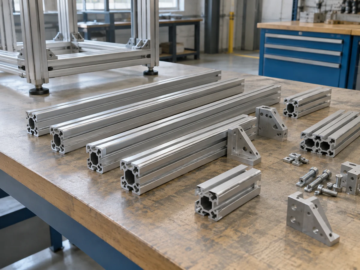
For each length, name the physical contact or datum that matters at the next operation. A nominal outer frame dimension is not automatically the cut length of every rail. Corner hardware, end caps, machining allowances and assembly sequence can change the released member length. If the drawing does not resolve those relationships, ask the fixture designer before treating the dimension as a saw setting.
Which end conditions do inspection fixture frames require?
Group jobs by end condition rather than by a single broad label such as aluminum frame. A square end, a repeated miter and an end needing later drilling are different routes. Note whether both ends require a controlled angular relationship, whether the profile must be turned between cuts, and whether the referenced face remains accessible when clamped. Draw a small end-A/end-B sketch for any ambiguous member.
Record the longest stock, shortest accepted finished piece, longest finished member, actual cross-section orientations, and the stock support available at both entry and exit. Long extrusions can make handling and support more consequential than nominal blade diameter alone. Short pieces can expose clamping and safe collection limits. Ask the supplier to show the proposed machine with your real profile orientation and each relevant end condition; do not infer a capability from a different section or angle.
Keep later operations visible in the route. A saw can prepare an extrusion blank or cut-to-length member; it does not by itself make holes, install threaded inserts, bolt a frame, mount sensors, or qualify the fixture. Bosch Rexroth’s FRAMEpro description separately discusses frame design, parts lists, sawing and drilling, which is a useful reminder to list each operation in the quoted boundary.
What should the supplier trial prove?
Submit a compact but representative trial set: the most demanding retained profile, the smallest acceptable piece, a long member needing support, and a member with the most demanding two-end relationship. If a fixture family uses multiple alloys, surface conditions or profile sections, identify them separately. A successful cut in one extrusion cannot stand in for every stock state.
Agree in advance how the sample will be checked. Record part ID, drawing revision, stock lot or identification if available, requested orientation, required end geometry, measurement reference, sample count and receiving criteria. Inspect the cut faces and end condition after normal handling, and check fit only in the appropriate assembly context. Keep free-state part inspection distinct from a member restrained in a bolted frame; the inspection-state guide explains the difference.
Ask for the actual saw model and quoted configuration used in the trial, including clamping, feeding, angle setting, support, guarding, collection and any auxiliary equipment that affects the result. A video of another machine is orientation material, not a trial record. Ask who records the results, what happens to a failed sample, and whether the successful setting can be repeated for the planned mix without unquoted tooling or manual preparation.
Why frame fit is a separate acceptance gate
Good individual ends help assembly, but the finished fixture also depends on connectors, hole locations, bracket faces, tightening sequence, support, thermal environment, load and the installed inspection hardware. The frame owner should define how straightness, squareness, datum position and stability will be judged in the actual assembled and operating state. Those criteria belong in the fixture acceptance plan, not in a claim about saw feeding precision.
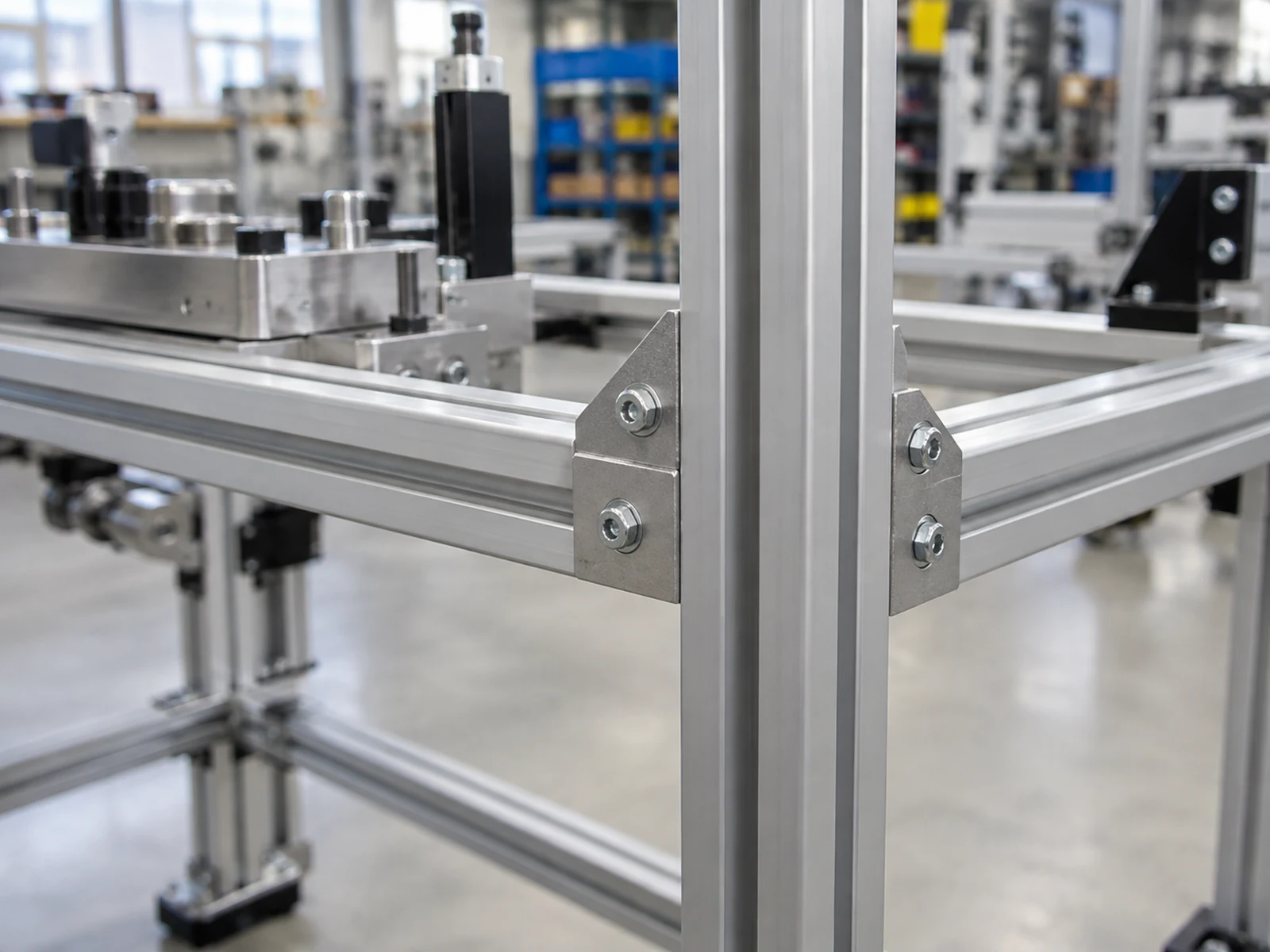
If the system will carry gauges, cameras, probes or locators, ask the responsible designer to define their mounting and calibration route. Do not use a saw trial to promise measurement uncertainty, repeatability or inspection yield. Those properties require a separate system-level method and evidence. This separation helps both sides quote the right equipment and prevents a cut sample from being over-read.
Capacity and workflow: count accepted frame packages
Estimate demand in member families and accepted fixture kits, not only in strokes per minute. List the fixture variants, members per variant, changeover frequency, required labeling, inspection, rework allowance and the point at which a complete kit is released to assembly. Then compare the proposed saw’s demonstrated production route with the actual time available for cutting and checking.
A faster saw can still leave the frame line waiting if stock staging, identification, drilling, hardware supply or inspection is the limiting step. Conversely, a controlled member schedule may make the cut operation predictable even when the assembled fixtures vary. Ask the supplier to state cycle assumptions and exclusions, then calculate throughput using your own accepted-package definition. Keep saw feed repeatability, part measurement and assembled-fixture performance as separate records.
Copyable RFQ package for an inspection fixture frame saw
- Fixture family, drawing revision, retained in-house work and receiving state of each member.
- Profile drawings, stock condition, actual orientation, member schedule, end-A/end-B sketches and length references.
- Quantity per fixture, batch mix, longest stock, shortest accepted piece, support and handling constraints.
- Connector, bracket, drilling, machining, assembly and measurement work explicitly outside or inside the proposed quote.
- Representative trial parts, inspection method, acceptance criteria and identification of the actual demonstrated machine configuration.
- Named ownership for frame assembly, sensor/locator installation, fixture qualification, maintenance and later revisions.
Request separate prices and scope for the cut-only route, prepared-member purchases and any complete-fixture alternative under consideration. Ask the supplier to identify unanswered drawing questions rather than silently choosing a datum, connector or end condition. That answer will tell you more than an unqualified machine capacity claim.
Equipment video: general example only
The following video is from Jiurun Machinery’s YouTube channel and shows general aluminum saw equipment in operation. It is an equipment-viewing example only. It does not show this inspection fixture material, the exact quoted model configuration, a customer fixture, a representative trial cut or verified accuracy, stability or throughput.
Next step: Send Jiurun the released member schedule, stock photos or drawings and your intended receiving state. Ask which actual saw configuration can be demonstrated against the named cut package, and keep the completed fixture’s measurement acceptance with the responsible system owner. Contact Jiurun with the RFQ package.