
An aluminum frame cut list should identify physical pieces, not every segment visible in the frame outline. A connection point can sit along a continuous member or mark a joint between separate members. Establish which construction is approved before releasing the lengths and quantities.
Aluminum frame cut list: a connection node is not necessarily a member end
Hypothetical purchasing case: a tooling factory needs a frame with a horizontal side member R running between endpoints P and Q. Side members S1 and S2 attach at intermediate positions N1 and N2. For this example, the factory’s design team has approved Arrangement A: R is one unbroken profile, with no splice at either attachment position.
The layout shows intervals P–N1, N1–N2 and N2–Q to locate those attachments. They describe positions within the assembly, not separate R components. These are invented schematic intervals; no particular CAD program is assumed to create or interpret them in this way.
item’s Technical Data for Profiles distinguishes attachments on an unbroken supporting profile from extending profiles with corresponding fastening elements. It describes different physical connection arrangements. That distinction does not make every intersection a cut or establish a structural recommendation for this fictional frame.
For A, P and Q define R’s ends. N1 and N2 remain attachment locations along it. The lengths and end requirements of S1 and S2 come from their own part definitions; their connections do not automatically create new ends in R.
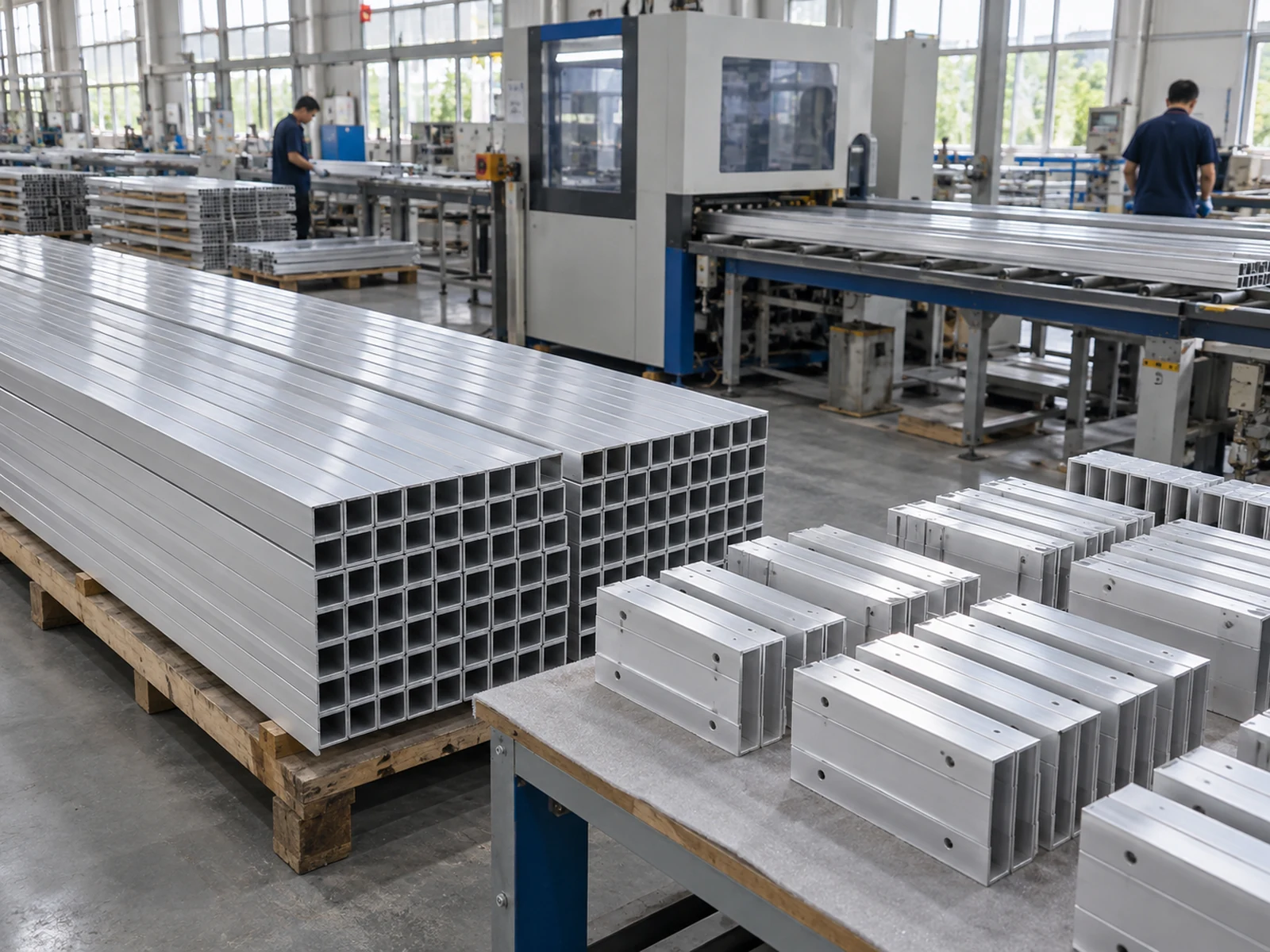
Compare the physical parts behind the same outline
Now suppose a purchasing assistant mistakenly lists the three schematic intervals as three short R pieces. Call that proposed list C. Even if their nominal lengths add up to the same apparent extent, the order would deliver separate pieces, not the approved continuous member.
C introduces two breaks where A specifies none. It does not supply the design for joining them, the required connecting items, any associated end preparation or the assembly work. Accurate cuts on those short pieces cannot turn them back into the single profile A requires.
Contrast C with a separately approved Arrangement B. B intentionally uses a segmented horizontal member with its own joints and component drawings. Multiple shorter pieces are correct for B because that construction is specified—not because an assistant divided A’s layout. Neither arrangement is presented as universally stronger, cheaper or preferable.
| Physical arrangement under review | What belongs on the cut list | Consequence of using the wrong piece boundaries |
|---|---|---|
| A — Approved continuous member R | One R from P to Q, with S1 and S2 listed as their separately defined members. | Dividing R at N1 and N2 introduces breaks absent from the approved arrangement. |
| B — Separately approved segmented member | The individual lengths and end requirements specified in B’s component drawings. | Using A’s graphic intervals instead can omit the actual joint-related part requirements. |
| C — Unapproved interval-based list | Resolve the physical members before releasing the assumed short pieces for production. | Layout intervals alone supply neither approval for additional joints nor the work needed to create them. |
The table compares the objects being purchased. It is not a guide to choosing connectors or calculating joint offsets. A real cut list needs the ends and lengths in the approved component definitions, not a sum reconstructed from the assembly’s visible outline.
Define the members before optimizing the stock
Once the pieces are established, assess how to obtain them from available stock. Planning several parts from one source bar is different from replacing one required part with several short pieces. The latter changes the delivered object, not merely the cutting arrangement.
Bosch Rexroth’s FRAMEpro page describes placing selected profiles and accessories in a line model, then generating a parts list that includes the required cutting and drilling for the constructed profiles. This concerns its configured profile system, not a guarantee about a generic drawing export.
C is an invented interpretation error, not a reported software fault. The example does not test FRAMEpro or claim compatibility with a JiurunCut machine. The buyer’s actual modeling and export behavior remains unknown.
If a stock proposal offers only shorter material than R requires, raise that mismatch before assigning cuts. The supplier must assess availability and the proposed sawing route for the actual continuous member. An attractive layout of shorter pieces does not authorize a splice or settle the missing long-member requirement.
Buy the approved member or release a different assembly first
Keeping A means purchasing one continuous R for each required assembly, together with its side members. If the factory wants to use a segmented alternative, its responsible designer must first approve that alternative and define the resulting parts. Purchasing cannot silently turn A into B to suit shorter stock.
For B, order B’s actual members and keep the specified connection and end-preparation work assigned. Do not derive its component lengths by dividing A’s span: the joint arrangement and its end requirements belong to B’s own definition.
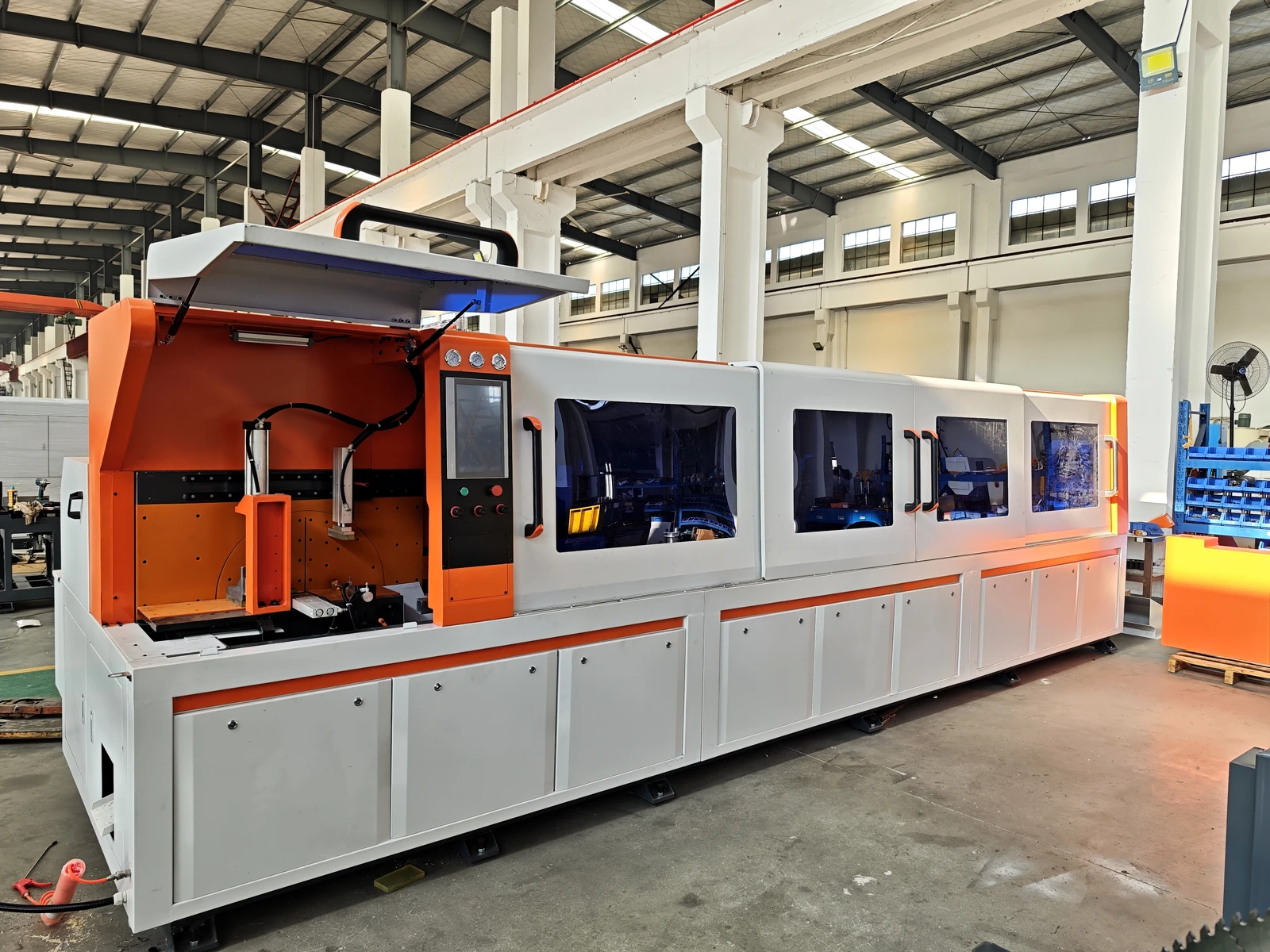
A focused clarification for the fictional A order could read:
R is continuous from P to Q. S1 and S2 connect at N1 and N2 without dividing R. Please base the cut-piece quantity on those physical boundaries, not the layout intervals. If the offered stock or cutting route has not been confirmed for the full R member, identify that open point rather than substituting joined short pieces.
This gives procurement a concrete comparison: an offer supplying the approved long member is not the same delivery as a collection of shorter pieces. If feasibility remains unresolved, request the actual supplier assessment rather than assuming either that the job is impossible or that any long-feed saw will cover it.
The selected material, complete member dimensions and end requirements still need equipment-specific review. Nothing in the schematic establishes available stock length, saw handling capacity or assembled-frame performance.
Send the physical members your frame actually needs
Share the approved member drawings, actual aluminum sections and required quantities of long and short pieces with JiurunCut. Identify which nodes are attachments and which are genuine member ends.
Discuss My Approved Frame Cut List
Ask what can be assessed for the specific circular-saw proposal. JiurunCut’s long-member suitability, end-processing scope and any automatic list or assembly functions remain unverified; this article does not approve the frame design.