
For pre-punched aluminum profile cutting, specify the finished length together with any required hole-to-end positions. Cutting equal lengths from a repeating hole pattern does not, by itself, preserve the same end distances on every piece. Decide whether to use the existing holes within an approved part layout or create the holes after cutting.
Start with the holes already in the stock
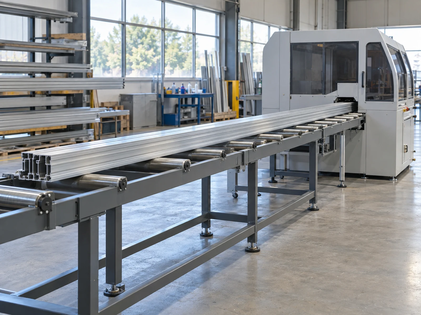
West Coast Products’ Framing & Material documentation describes aluminum tubes, angles and channels supplied with repeating punched holes for assembly in its robotics framing range. This is an example of pre-punched stock, not a JiurunCut application or the source of the fictional dimensions below.
Hypothetical purchasing case: a factory wants repeated assembly members from a straight, pre-punched aluminum profile. Its initial request specifies the member length, but the part drawing also controls the first and last hole positions relative to the ends. The buyer needs both conditions to survive the proposed cutting layout.
The existing holes belong to the incoming stock; they are not created afresh for each retained piece. A reply confirming cut length alone therefore leaves part of this fictional factory’s output requirement unanswered.
Equal lengths can leave different end-to-hole distances
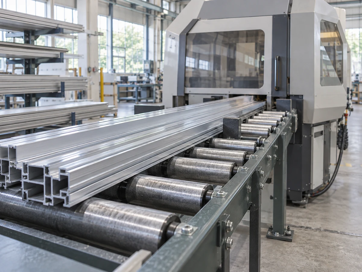
Every dimension and coordinate in this example is invented. None is a supplier specification, JiurunCut setting, trial result or recommended design clearance. The model assumes exact cut locations and no feeding-position error. It specifies no hole diameter, wall thickness or loading requirement.
Imagine a coordinate along the straight stock. Hole centres lie at 20, 60, 100, 140, 180, 220 mm and continue at a 40 mm pitch. Each retained piece is 200 mm long, with an assumed 3 mm kerf between adjacent retained intervals.
The hypothetical retained intervals are A: [0, 200] mm; B: [203, 403] mm; and C: [406, 606] mm. These intervals explain the geometry; they are not cutting instructions. All end distances below run from the retained ends to hole centres, not to the edges of the holes.
| Hypothetical retained piece | First hole centre from its starting end | Last hole centre to its finishing end |
|---|---|---|
| Piece A — 200 mm | 20 mm | 20 mm |
| Piece B — 200 mm | 17 mm | 23 mm |
| Piece C — 200 mm | 14 mm | 26 mm |
For B, the first retained hole centre is at stock coordinate 220 mm: 220 − 203 = 17 mm from the starting end. The last is at 380 mm: 403 − 380 = 23 mm from the finishing end. For C, the corresponding differences are 420 − 406 = 14 mm and 606 − 580 = 26 mm.
All three pieces remain 200 mm long and each contains five hole centres. The difference arises because successive retained starts advance by 203 mm while the holes repeat every 40 mm. The kerf changes where the next piece begins within that repeating pattern. Neither the holes nor the machine have been assumed inaccurate.
This is not a claim that every pre-punched stock layout produces the same problem. The actual pattern, retained intervals and kerf must be considered together. Buying a specified length is a narrower requirement than buying that length with specified hole positions at both ends.
In its rail-joining example, igus relates the end-to-hole position to mounting-hole spacing across the joint. That is a product-specific example of why this relationship can matter, not a universal requirement for symmetric ends or a minimum edge distance on aluminum profiles.
Choose between existing holes and holemaking after cutting
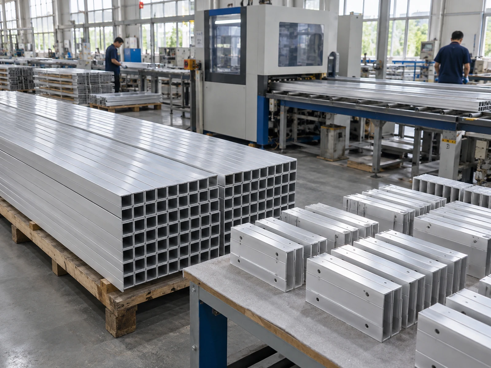
Use the pre-punched stock within a defined part layout. This route remains worth considering when the component design can use the existing array. Have the responsible parties confirm a layout that meets the required length and hole-to-end relationships together. Do not assume that avoiding a later holemaking operation makes every consecutive equal-length piece the same assembly component.
If that approved layout calls for extra material to be excluded or different retained boundaries, include those consequences in the production comparison. This article provides no universal trimming amount or alternative cut pattern. The decision needs the real stock and part requirements, not the fictional coordinates above.
Cut unpunched blanks and make the holes afterward. This route leaves the hole pattern to a separately specified operation on the cut pieces. The factory must assign that holemaking work and its acceptance check. A saw-only offer does not include them merely because the final drawing shows holes.
Neither route is automatically more accurate, cheaper or more material-efficient. Compare the work each provider actually delivers and the remaining operations the factory must arrange. A supply of plain blanks and a supply of parts with the required holes are not equivalent outputs.
If the purchased pieces already have their final holes and ends completed to the part drawing, confirm that incoming state before adding another cut. Further shortening could change the required relationship. The equipment purchase should address work that actually remains, not introduce a second cutting stage by assumption.
Evaluate the output required from the saw
Where overall length is the only controlled cutting requirement and the assembly accepts the resulting hole positions, do not add hole-referenced features that the job does not need. Where both end relationships are specified, ask the supplier to assess the actual pre-punched section and the buyer-approved retained-piece layout.
In the fictional model, showing Piece A alone would not reveal the different end distances in B and C. A demonstration of correct total length would likewise leave the complete mounting-part requirement unanswered. This is a reason to describe the required output, not a diagnosis of a machine fault.
A buyer could return this clarification:
The incoming profile already contains the repeated hole pattern shown in our material reference. Our required output includes both overall length and the specified first/last hole positions relative to the ends. Please assess the proposed retained-piece layout against those requirements. Identify whether your offer addresses this pre-punched input or supplies plain blanks for separately arranged holemaking. Keep unassessed workpiece or configuration requirements explicit.
The supplier’s response should address the intended physical result. It must not be assumed to include hole detection, positioning from existing holes or automatic changes to cut locations. Actual workpiece suitability and any such functions need their own evidence for the offered configuration.
Discuss the required cutting output with JiurunCut
Share the actual profile section, existing hole-pattern drawing or identified sample information, and the required relationship between the retained ends and holes. State whether the input is pre-punched stock or a plain blank with holemaking assigned later.
Discuss My Pre-Punched Profile and Required Ends
Ask what can be assessed for the specific circular-saw proposal. This article does not establish JiurunCut’s suitability for the part, automatic hole recognition or positioning, drilling/punching capability, or availability of a trial.