
A surface texture direction value needs its reference axis and evaluation area. Keep the parameter name and reporting convention with the angle. A number such as “30 degrees” does not identify its relationship to the part drawing by itself.
For an aluminum blank or finished component, confirm which face was evaluated and how the measurement coordinates relate to the part. This makes the supplier’s report easier to compare with the actual requirement.
On this page
1. Keep the surface texture direction parameter name
KEYENCE’s Std* explanation describes a texture-direction angle associated with the largest value in the angular spectrum. The page connects that angle to surface lay.
Keep the report’s complete parameter label, including its notation and method reference. Do not assume that every field labelled “direction” uses the same calculation or convention.
A direction field answers a different question from a height field. Preserve both headings where the drawing requires both. An angle does not replace a roughness-height requirement.
The Ra versus Sa guide addresses height reporting along a profile or over an area. This article concentrates on the reference behind a direction entry.
If the instrument report uses an unfamiliar abbreviation, ask the laboratory to provide the definition and applicable interpretation. Keep that explanation linked to the report version rather than replacing its label with a guessed equivalent.
The KEYENCE page is explanatory manufacturer guidance. Use the actual agreed method and applicable document edition for acceptance; this guide does not reproduce a full measurement standard.
2. Locate the area behind the result
KEYENCE’s area-roughness terminology distinguishes the evaluation area from the definition area used for parameter calculation. It also connects the angular spectrum to the direction of the surface pattern.
Ask for the measured face and area location on a labelled part view. Retain the relevant area dimensions and the processing information specified by the laboratory’s method.
An area near one feature and an area on another face are separate locations. A general note such as “top surface” becomes ambiguous when the component can be turned over.
Use the part identifier and drawing revision with the location. A report may be perfectly legible yet refer to an earlier part or a different selected face.
If several areas were evaluated, keep each result connected to its own area label. Do not attach the last recorded angle to every location in a summary.
Ask the laboratory how the reported direction is interpreted for the evaluated texture. Where a result does not provide a clear directional interpretation, preserve that qualification instead of reporting a confident angle without support.
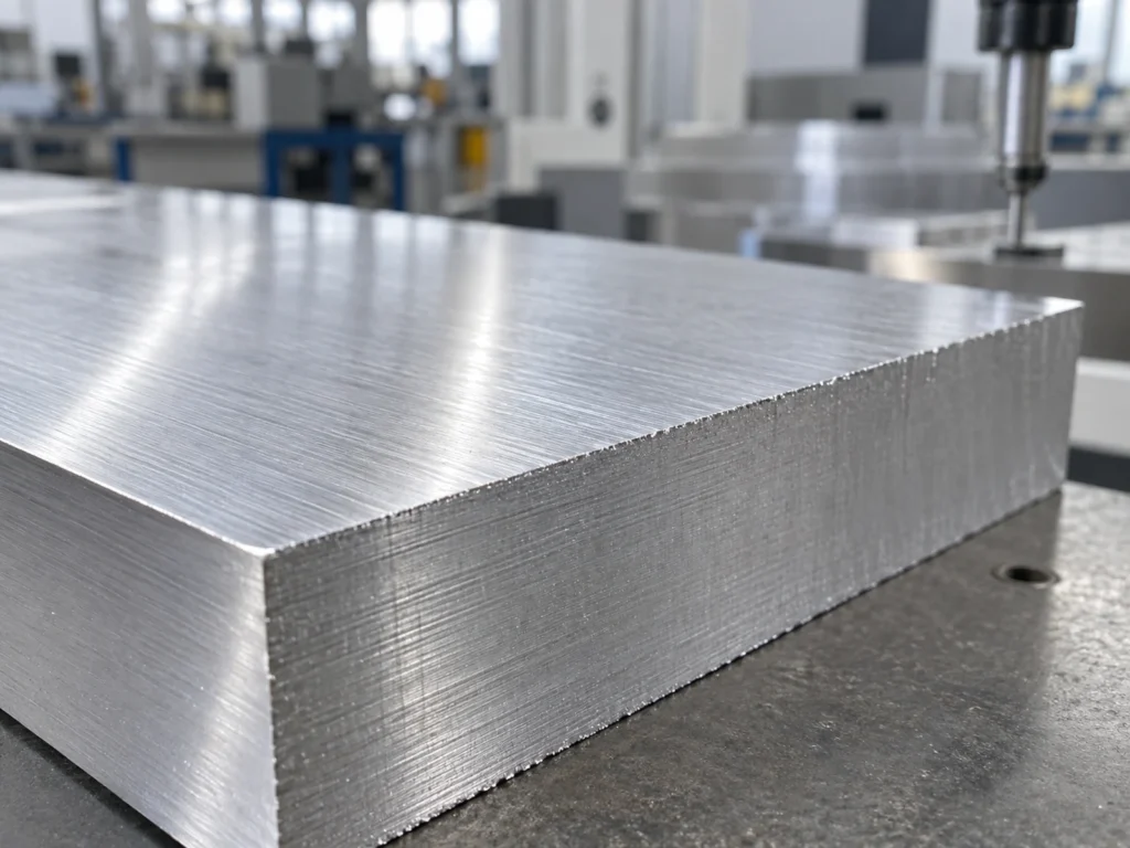
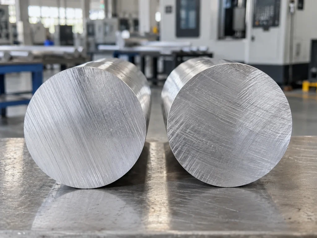
Keep visible appearance evidence separate. An editorial photograph may show lines, but it does not provide the processed height data, evaluation definition or parameter result needed to reproduce the report.
3. Identify the reference for an angle
Request the coordinate reference used in the report. Identify how its axes align with a named part edge or feature, and which viewing direction is used.
Keep the angle unit, zero reference and positive direction together. If the report provides a particular angle range or orientation convention, retain it. Ask the laboratory to explain any transformation into the part drawing’s coordinates.
Do not assume the instrument’s screen horizontal is the drawing’s reference edge. The component may have been placed differently for measurement, and the displayed view needs its own orientation identification.
A rotated image can change how a line appears on screen. Preserve the original report view and its reference information so a presentation change does not become a supposed change in the evaluated part.
Have the responsible reviewer resolve any difference between the drawing’s convention and the report’s convention. This guide gives no universal conversion rule for every instrument’s texture-direction output.
An original coordinate example
Imagine a drawn line on a fictional part diagram. Define Edge A as the zero direction. Define counterclockwise angles as positive in this particular view.
Now draw a local X reference 10 degrees counterclockwise from Edge A. Draw the line another 30 degrees counterclockwise from that local X reference. By the stated diagram convention, the line is 40 degrees counterclockwise from Edge A: 10 + 30 = 40.
| Reference | Angle to the drawn line |
|---|---|
| Local X reference | 30 degrees counterclockwise in the defined fictional view. |
| Part Edge A | 40 degrees counterclockwise in that same view. |
The line has not moved between these two descriptions. The reference changed. Comparing only “30” and “40” would miss that distinction.
This is simple, invented diagram geometry. It is not a Std* algorithm, an actual aluminum measurement or an instruction to add offsets to an instrument result without reviewing its convention.
Keep three direction records separate
A surface texture direction entry describes a surface-pattern quantity under its reporting method. A required finishing direction and a material-direction requirement need their own explicit definitions.
For rolled material, the grain-direction guide explains why a visible pattern does not prove the source rolling direction. Keep that source identification with the material record.
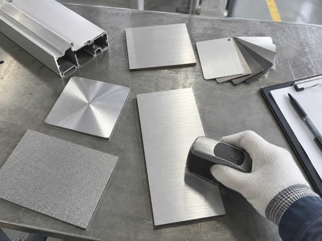
If an appearance requirement uses a brushed finish, retain the approved face and reference sample. A numerical texture-direction report does not automatically establish every cosmetic acceptance feature.
State which requirement the report is meant to evaluate. This prevents one direction field from silently answering three different questions.
A clear request to the measurement supplier
Request the parameter definition, original result, evaluated-area map and coordinate reference. Keep the method and processing information with the report, along with its specimen and revision identifiers.
If the result is transferred into a quotation summary, retain a link or reference to the complete record. Mark missing location or reference information as pending rather than filling it from a product photograph.
Have the responsible technical authority compare the defined result with the approved requirement. The final decision should identify the part, face and scope reviewed.
Buyer questions
Does an angle describe roughness height?
Preserve the separate quantity headings. A direction entry does not supply a height value.
Can a surface photograph identify rolling direction?
Use the material supplier’s source identification. A visible finish pattern is not that record.
Can I compare two direction angles without their axes?
Request their references and conventions first. The fictional example shows why the numbers alone leave the relationship unresolved.
Make the cutting and later finishing scopes clear
Send JiurunCut your aluminum stock drawing, cut dimensions and quantities. Identify any later-operation handoff affected by surface texture direction, while keeping the measurement definition and acceptance review with the responsible supplier.