
Left hand vs right hand threads differ in the direction of their helix. Keep that direction with the complete thread designation and the identified feature. Matching nominal diameter and pitch alone does not establish that two threads will mate.
For threaded aluminum parts, begin with the released drawing. For a machine spare, begin with the manufacturer’s identified replacement. This guide helps a purchasing team keep the direction readable in those records.
Three distinctions to preserve
- Thread hand belongs to a particular internal or external feature.
- A rotation description needs a stated viewing direction.
- A left or right assembly position does not identify thread hand.
On this page
1. Give left hand vs right hand threads a feature identity
Identify the hole, stud or other threaded feature before shortening its description into a quotation line. Preserve the thread family, size, pitch, required fit information and direction from the drawing.
Accu’s thread-handedness guide describes right-hand and left-hand threads as opposite helix directions. It notes the use of LH to identify a left-hand thread on a drawing. Its explanation also distinguishes mating threads from a product that contains both directions at different features.
Let the applicable drawing convention define the actual callout. The point for purchasing is to retain the complete released information, including an explicit LH requirement where present. Do not drop that suffix when copying the size into a spreadsheet.
Give two threaded ends separate feature identifiers. “Both ends threaded” leaves the relationship unclear if the ends have different requirements. Link each identifier to its complete definition.
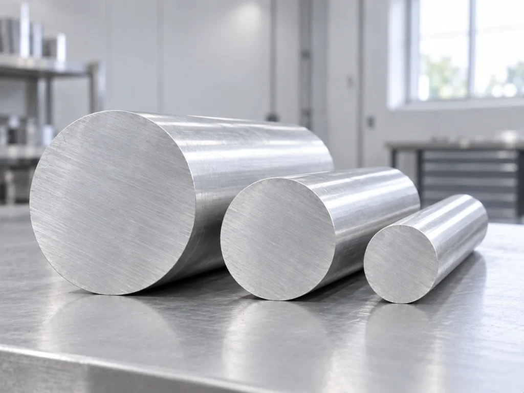
For left hand vs right hand threads on aluminum components, state which manufacturing stage supplies them. A saw-cut blank and a body with completed internal threads are different delivery scopes. Preserve the handoff to the later operation.
2. State the viewing direction for a rotation description
For a simple explanatory view, look from an external screw’s head toward its tip, with the mating internal part stationary. Under that defined view, a right-hand screw advances away from the observer when turned clockwise; a left-hand screw advances away when turned counterclockwise.
Accu’s guide explains these opposite directions. Keep the reference view visible when using a rotation note. Looking from the opposite end changes how a motion appears to the observer; it does not change the physical thread’s hand.
This distinction helps your team read a document consistently. It is not a service instruction for a machine nut, spindle or blade-retaining component. Use the actual manufacturer’s identified part and procedure for those tasks.
A label such as “right-side bracket” describes the assembly position. It does not, by itself, say that the bracket’s hole has a right-hand thread. Keep the position label and thread requirement as separate entries.
Likewise, mirroring the placement of two members in a drawing does not authorize changing a specified thread. Have the drawing owner define the actual handed features. A purchasing summary should report that decision accurately.
One feature, two observer positions
Imagine a fictional screw and mating hole labeled feature F. Reviewer A reads the agreed head-to-tip view. Reviewer B is looking from the far side of the assembly. A casual instruction saying “turn left” can be interpreted differently by these observers.
Recording feature F, its complete thread designation and the reference view removes that wording ambiguity. No torque value, machine movement or actual component is defined in this example.

3. Match the hand at each mating interface
Accu states that opposite thread hands do not directly mate. A component can nevertheless contain a right-hand feature and a left-hand feature at different locations. Keep those locations separate when reviewing the supplied pieces.
When comparing left hand vs right hand threads, match each internal feature with the external feature intended to engage it. The complete requirements still include the other specified thread characteristics. Shared direction alone is not complete compatibility.
An original two-ended body example
Assume a fictional connector body P with two internally threaded ends. The released teaching definition labels end A as right-hand and end B as left-hand. Both share the same nominal diameter and pitch; the actual thread family and other requirements remain in its controlled definition.
| Feature in the example | Identity to retain |
|---|---|
| Body P, end A | Its specified internal right-hand thread and corresponding mating external feature. |
| Body P, end B | Its specified internal left-hand thread and corresponding mating external feature. |
Now assume a fictional order for 24 completed bodies. The feature list contains 24 end-A threads and 24 end-B threads. A record listing only 48 holes loses which requirement belongs to which end.
If a proposal supplies 24 cut blanks instead, neither completed thread group is included unless the agreed scope says so. The quantity of bodies remains 24, but the supplied manufacturing stage has changed.
These counts illustrate a document distinction. They do not specify a real connector, tool path or assembly approval. For the actual order, retain both end identities beside the drawing revision.
Use our thread inspection guide to define the required evidence for those identified features. Keep the end-A result separate from the end-B result so a general “threads checked” statement has a clear scope.
Keep left hand vs right hand threads readable in the order
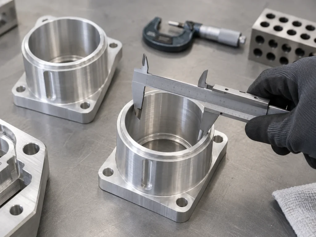
Send the controlled feature definitions with the purchase request. Keep the end labels, direction requirements and supplied stage visible in the quotation and receiving records.
Ask the supplier to identify any proposed substitute before release. Do not accept a shortened size description as confirmation that the direction matches. Record the responsible approval against the actual feature definition.
For a cut blank requiring later threading, show which end and surface references the next operation uses. Our extrusion end-tapping guide covers that handoff information.
For an existing machine’s spare, request the exact identified replacement reference and compatible configuration. A familiar nominal size or a visible direction arrow is not a complete replacement specification.
Common questions about left hand vs right hand threads
Does “left-side part” mean a left-hand thread?
No. It names an assembly position unless the released definition also states the thread requirement.
Can opposite thread hands mate directly?
No. Preserve the specified direction at each mating interface and review the complete thread characteristics.
Can one body contain both directions?
Yes, at separately defined features. The fictional body example shows why each end needs its own identity.
Define the blank and downstream feature scope
Send JiurunCut the aluminum drawing, cut lengths and quantities. If left hand vs right hand threads matter in a later operation, include the feature definitions and state which stage the cutting quotation should supply.