
Vacuum clamping aluminum starts with the actual contact face and the complete operation. A broad-looking part does not tell a buyer how much area is sealed, how the part resists sideways loads or what happens when its geometry changes during machining.
For a purchase review, request a workpiece-specific proposal. Keep the clamping interface, vacuum supply and machine integration in the same scope, with a named party responsible for validating the application.
On this page
Understand the principle of vacuum clamping aluminum
Schmalz describes vacuum clamping as holding a workpiece through a pressure difference across an effective sealed area. Its explanation distinguishes the holding action normal to the surface from resistance to sideways forces, which also involves the friction at the interface.
The same source identifies sealing as a condition of achievable holding force. Leakage, small contact areas and unsuitable surfaces can limit the arrangement. These points support an application review; they do not establish that a particular aluminum part is suitable.
Ask the supplier to state what its quoted force represents. Is it a theoretical normal force, a lateral value under stated conditions or a result from an identified application trial? Keep those descriptions separate in your comparison notes.
Our aluminum saw clamping guide covers profile restraint and equipment scope. This article addresses a different question: how to review a proposed vacuum interface and the assumptions behind its holding claim.
Separate the footprint from the effective area
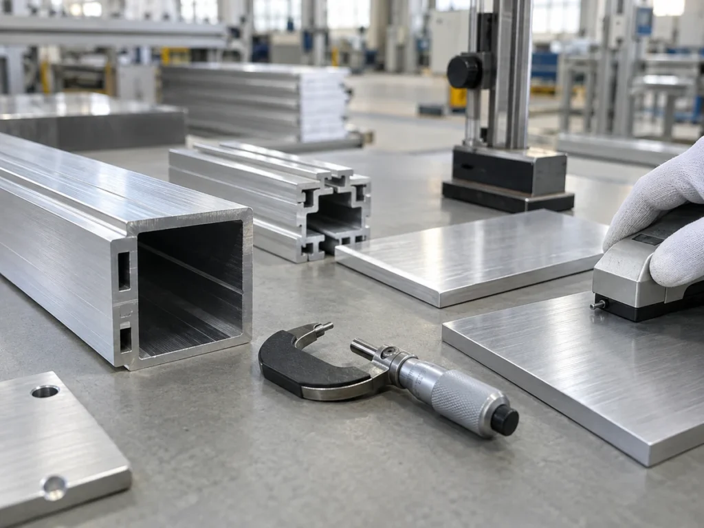
Put both dimensions on the proposal. The overall outline helps identify the workpiece. The proposed sealed region identifies the area used in the supplier’s assessment. Ask for a sketch with the relevant boundaries and excluded features.
Schmalz’s suction-cup design guidance defines effective suction area and treats force calculations as theoretical. It also states that friction depends on the actual surface and contact material, with trials needed to determine it. A catalog diameter and a guessed friction value do not document an approved machining setup.
Original geometry example: two different rectangles
Consider a fictional flat blank with a 200 × 100 mm outer outline. Its footprint is 20,000 mm². A proposed contact sketch identifies only a central 120 × 60 mm rectangular region for review. That rectangle is 7,200 mm², or 36% of the footprint.
The arithmetic is 120 × 60 ÷ (200 × 100) × 100 = 36%. It simply compares two nominal areas. It does not confirm that the smaller rectangle is actually sealed, calculate a holding force or authorize a cutting load.
| Drawing item | What the number establishes |
|---|---|
| 200 × 100 mm outline | A fictional overall footprint of 20,000 mm² |
| 120 × 60 mm review region | A fictional nominal rectangle of 7,200 mm² |
| 36% area ratio | The relationship between those rectangles, without a force rating |
A useful quotation names the actual interface rather than copying the overall part area into a force field. If that interface is still being developed, identify the calculation as provisional and keep the approval status visible.
Compare three workpiece descriptions
These are fictional inquiry examples. None includes a successful trial or an approved fixture. Their purpose is to show which missing information a buyer should request.
Case A: a plain aluminum blank
The inquiry includes an outline and thickness but does not identify the contact face. Return a marked drawing request. Ask which side is proposed for contact, what its delivered condition is and which drawing controls that condition.
Keep the blank preparation scope separate from the fixture scope. A supplier of cut blanks needs the material identity, finished dimensions and agreed inspection references. The fixture designer needs the operation and interface information as well.
Case B: the part changes during the operation
The drawing shows an initial blank and a finished component with additional openings. Ask the application reviewer to identify the geometry covered by the proposed assessment, including the intermediate stages that matter to the fixture.
Do not carry an approval from the starting blank into a different part condition without review. Put the relevant drawing states in the trial package so the responsible team can judge the proposed operation.
Case C: a different supplied surface
A repeat order keeps the same part number, but the contact face has a changed finish specification. Record that change and send it to the clamping supplier. Ask whether the existing application evidence covers the new condition.
The supplier’s answer might require additional review. Keep the order status clear until that question is resolved. A matching outer dimension is not a record of matching surface conditions.
Read the complete system scope
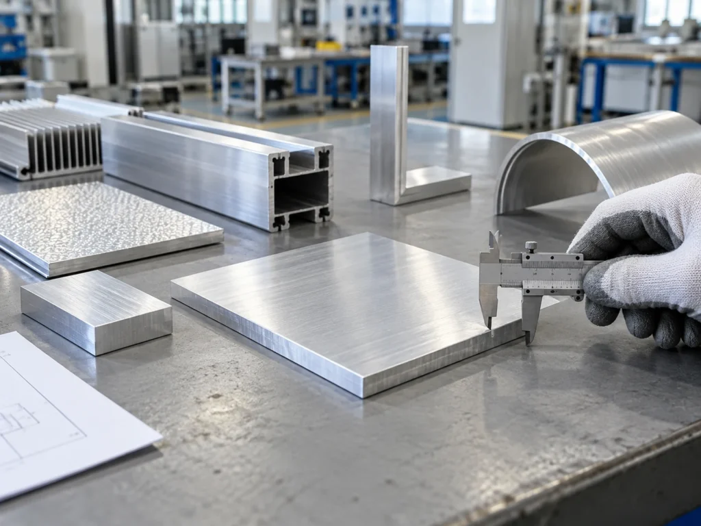
Schmalz identifies the contact equipment, vacuum generation, distribution and monitoring as parts of a coordinated clamping system. Use that distinction to request separate supply lines rather than a single unexplained “vacuum table” entry.
- Contact equipment: identify the fixture or interface drawing and the covered parts.
- Supply equipment: identify the proposed vacuum source and included connections.
- Integration: name the party responsible for the machine interface and approved response to a loss of clamping condition.
- Documentation: list application approval, operating documents and replacement-item identification.
Ask whether each line is included, optional or supplied by another party. Where two suppliers share an interface, attach one agreed responsibility note to both offers. This keeps a missing integration item from appearing only after delivery.
Do not assume that a JiurunCut saw includes a vacuum system because it is mentioned in a buyer guide. Confirm the actual proposed machine configuration. Vacuum workholding on another operation may require a separate specialist review.
Agree on application evidence before release
Write a review plan that identifies the workpiece, interface, operation and acceptance documents. Keep the proposed setup conditions attached to the results. The review team should be able to tell which part revision was evaluated.
Include the required finished-part observations, such as the drawing dimensions and specified surface condition. Use the thin-wall profile review guide for the separate question of section support and post-fixture inspection.
Ask how changes will be handled after approval. A different contact component, part finish or drawing revision should have a clear review route. Record who decides whether new evidence is needed, rather than leaving that decision implicit.
Purchasing questions about vacuum clamping aluminum
Can I compare two systems using only the stated holding force?
First identify the type of force, conditions and approval scope. Compare supported application statements for the same workpiece and operation, with unresolved differences recorded.
Does a large panel outline establish its sealed area?
No. Request the proposed contact boundary and the identified effective area. The fictional rectangle comparison illustrates why overall size and the reviewed region can differ.
Can a previous trial approve a changed part?
Ask the responsible application reviewer. State the change clearly and obtain a written decision on the evidence needed before releasing the new scope.
Prepare a focused inquiry
Send JiurunCut your aluminum cutting requirements with the section or blank drawing, quantities and finished-part requirements. If a vacuum arrangement is being proposed elsewhere in the process, identify its supplier and the interface under review. Keep the cutting proposal and specialist fixture approval clearly documented.
Technical references
Schmalz: vacuum clamping technology explains the principle and system elements. Schmalz: suction-cup design discusses theoretical force and interface conditions. The rectangle example and inquiry cases are original purchasing aids.