
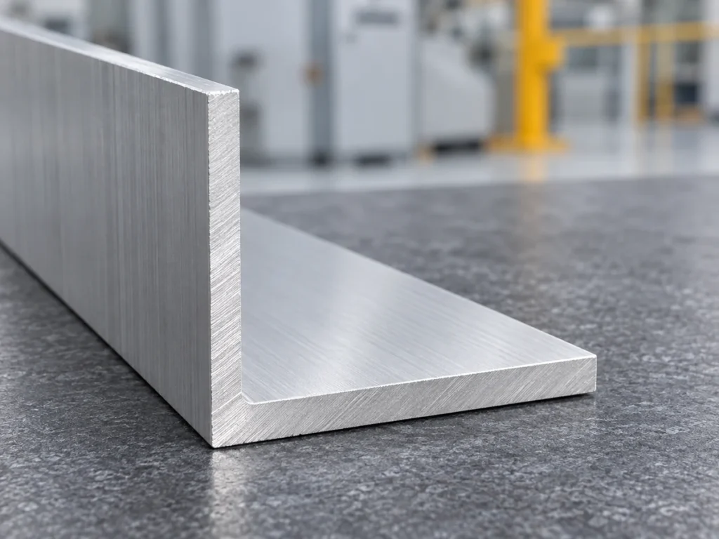
Aluminum extrusion corner radius belongs to the profile’s cross-section. It can affect how a bracket, insert or other mating part sits against that section. A general description such as “square tube” or “equal angle” does not define every corner feature.
For a cutting order, keep the stock’s longitudinal corner geometry separate from the treatment of newly cut end edges. The profile drawing controls one; the cut-part requirements control the other. Five fields help buyers communicate that distinction without guessing a radius from a photograph.
Before approving a stock substitute
- Identify the exact inside or outside corner on the section drawing.
- Check the radius and adjacent geometry with the mating part.
- Keep profile radii separate from cut-end deburring or chamfering.
On this page
1. Identify the aluminum extrusion corner radius on the section
Mark the specific corner that matters: an inside junction, an outside round, a slot opening or another feature. Point the requirement to that feature on the complete section drawing. A note that says only “corner radius” can refer to more than one place.
Autodesk’s fillet documentation distinguishes rounding exterior edges from adding fillet geometry at interior edges. For procurement, the useful distinction is which material boundary the dimension controls. The two locations should not be swapped in a supplier comparison.
Use the drawing’s own legend when reading R, R1 or other identifiers. Those symbols must connect to the shown feature; do not assume that a particular subscript always means an inside or outside corner in every catalog.
If several corners share one requirement, the controlled drawing should show that scope. If they differ, record each relevant feature separately. Keep an enlarged detail when the main section view makes the leader ambiguous.
2. Define the corner geometry and dimension
A radius describes a circular arc’s size. A chamfer describes a different corner geometry. In Autodesk’s sketch-tool reference, a fillet is an arc of a specified radius, while chamfer tools use distance or distance-and-angle definitions.
That distinction matters when a supplier proposes “breaking the corner.” Ask whether the proposal changes a longitudinal profile feature or treats the cut end. Neither an unspecified edge break nor a bevel is automatically equivalent to the required profile radius.
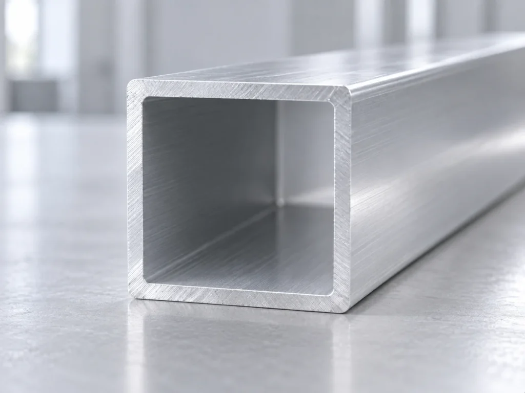
Hydro’s City of Industry shape catalog separates sharp-corner and round-corner rectangular and square tubes. This is useful evidence that the broad tube description can contain different corner configurations. Compare the exact profile record and section drawing before approving a replacement.
A catalog category is not a promise of a mathematically zero-radius physical edge. Ask for the governing dimension and tolerance when that corner affects function. Keep the stock supplier’s confirmed requirement with the part record.
3. Keep radius, units and revision together
Record whether the drawing value is a radius or a diameter, and confirm the units. Radius and diameter are different dimensions: a circle with radius 3 mm has diameter 6 mm. That simple example explains notation, not an extrusion manufacturing limit.
Do not transfer a number from a supplier’s table without its heading and section sketch. Also check whether the current approved drawing has replaced an earlier value. A correct unit conversion can still reproduce an obsolete requirement.
If the source uses inches and the receiving drawing uses millimeters, preserve the original value and the controlled conversion basis. Avoid rounding a converted dimension into an unapproved tolerance. Our inch-to-millimeter guide explains the difference between conversion and acceptance.
When an aluminum extrusion corner radius is left unspecified on an incoming drawing, ask the design owner to identify the controlling requirement. A supplier’s usual profile or a cropped image should not silently become the new definition.
4. Review the mating space and intended contact
An inside fillet occupies part of the space near a junction. A mating piece that is expected to reach both adjacent faces needs a compatible local shape. Check the complete pair of geometries rather than comparing only outside width and height.
For example, an insert can match the nominal internal width of a tube while its corner shape still needs review. This is a possible fit issue, not a claim that every square insert will interfere. The controlled drawing, permitted variations and intended assembly position determine the result.
Identify which faces are intended to contact and where clearance is required. A designer may choose a relieved mating corner or another interface arrangement, but the change needs approval. Do not ask receiving to file away a corner to make an unapproved substitute fit.
For slotted frame connections, our T-slot hardware compatibility guide explains why nominal profile size alone is insufficient. The same purchasing discipline applies when a corner feature belongs to a bracket or insert interface.

5. Separate stock geometry from cut-end acceptance
Cutting a long extrusion to length exposes its cross-section at a new end. Deburring that end is a separate operation from specifying the extrusion’s corner geometry. Write both requirements when both matter.
If an offer includes a chamfer or an edge break on the cut piece, identify its location and acceptance basis. Do not assume that it changes a stock corner running along the profile. Our deburring and chamfer guide helps define that cut-part scope.
The inspection plan should identify which stage verifies the relevant feature. Stock acceptance, cut-part acceptance and assembly review can answer different questions. A successful length measurement does not establish a radius or mating clearance.
| Feature to review | Required reference |
|---|---|
| Longitudinal inside corner | Approved stock-section dimension and variation. |
| Longitudinal outside corner | Its own marked feature and acceptance basis. |
| New cut-end edge | Cut-part deburring, chamfer or edge-break requirement. |
A fictional mix-up: the wrong corner has the right value
Imagine a profile drawing defines an inside radius of 2 mm and an outside radius of 4 mm at a particular junction. A purchasing spreadsheet records only “R4,” and another supplier interprets that as the required inside feature.
The number is present, but its identity has changed. A clearer record names the inside feature, its 2 mm radius, the units and the drawing revision. It records the outside feature separately when needed. These fictional values illustrate a documentation error, not standard extrusion radii or a recommended design.
If the supplier proposes a different corner, send the marked section and the mating-part information to the design owner. Hold the substitution decision until the actual interface requirement has been reviewed.
A clearer record for aluminum extrusion corner radius
Keep the profile reference, drawing revision, marked corner, dimension type, units and governing variation together. Add the mating feature and the supplied stage when they influence acceptance. Attach the full section rather than a visual approximation.
This record allows the stock supplier to discuss the actual feature and the cutting supplier to preserve the intended orientation and surfaces. It also gives receiving a defined question instead of asking whether the corner “looks about right.”
Buyer questions
Can I read aluminum extrusion corner radius from a photograph?
A photograph may show a rounded feature, but it does not supply a controlled dimension or tolerance. Use the approved section drawing and the required inspection method.
Does equal outside size prove two profiles have the same corner geometry?
No. Compare the relevant internal and external features, their allowed variation and the mating-part requirements.
What should I send for a cutting review?
Send JiurunCut the approved stock section, cut drawing, quantities and the marked locating or protected faces. Keep any cut-end treatment separate from the stock profile radius requirement.